SLVSE94G September 2018 – June 2024 TPS2663
PRODUCTION DATA
- 1
- 1 Features
- 2 Applications
- 3 Description
- 4 Device Comparison Table
- 5 Pin Configuration and Functions
- 6 Specifications
- 7 Parameter Measurement Information
-
8 Detailed Description
- 8.1 Overview
- 8.2 Functional Block Diagram
- 8.3
Feature Description
- 8.3.1 Hot Plug-In and Inrush Current Control
- 8.3.2 PGOOD and PGTH
- 8.3.3 Undervoltage Lockout (UVLO)
- 8.3.4 Overvoltage Protection (OVP)
- 8.3.5 Input Reverse Polarity Protection (B_GATE, DRV)
- 8.3.6 Reverse Current Protection
- 8.3.7 Overload and Short-Circuit Protection
- 8.3.8 Output Power Limiting, PLIM (TPS26632, TPS26633, TPS26635, TPS26636, and TPS26637 Only)
- 8.3.9 Current Monitoring Output (IMON)
- 8.3.10 FAULT Response (FLT)
- 8.3.11 IN_SYS, IN, OUT, and GND Pins
- 8.3.12 Thermal Shutdown
- 8.3.13 Low Current Shutdown Control (SHDN)
- 8.4 Device Functional Modes
-
9 Application and Implementation
- 9.1 Application Information
- 9.2
Typical Application: Power Path Protection in a PLC System
- 9.2.1 Design Requirements
- 9.2.2 Detailed Design Procedure
- 9.2.3 Application Curves
- 9.3 System Examples
- 9.4 Dos and Do Nots
- 9.5 Power Supply Recommendations
- 9.6 Layout
- 10Device and Documentation Support
- 11Revision History
- 12Mechanical, Packaging, and Orderable Information
Package Options
Refer to the PDF data sheet for device specific package drawings
Mechanical Data (Package|Pins)
- RGE|24
- PWP|20
Thermal pad, mechanical data (Package|Pins)
Orderable Information
9.2 Typical Application: Power Path Protection in a PLC System
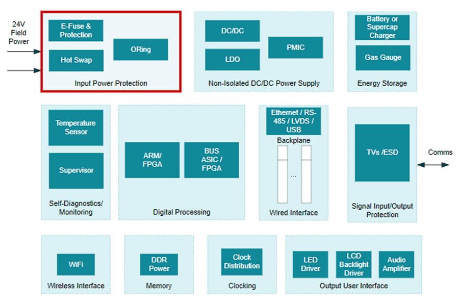
 Figure 9-1 A Typical CPU (PLC Controller) System Block Diagram
The PLC system is usually connected to an external 24-V DC power supply to provide power to the controller unit, backplane, and I/O modules. Input protection circuits are required to protect the PLC from faults such as overvoltage, undervoltage, and overload. Because input supply connectors are screw type, there can always be a possibility of reverse supply connections. Protection circuits must block the reverse polarity to protect the PLC from possible negative voltages. At the same time, every PLC is tested for electrostatic discharge (ESD) according to IEC 61000-4-2, burst pulses (EFT) according to IEC 61000- 4-4, energy single pulse (surge) according to IEC 61000-4-5, voltage drops and interruptions. Figure 9-1 shows a system block diagram of PLC controller unit along with the input protection socket. The TPS2663x devices offer a plug and play input protection solution for such applications. For more information about this end equipment, refer to the TI application site on Programmable Logic Controller (PLC), DCS & PAC: CPU (PLC Controller).
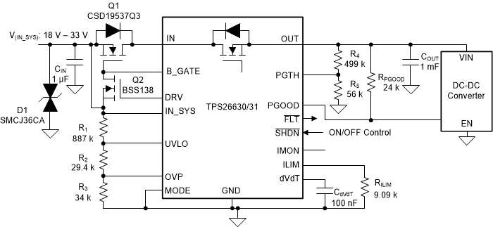
 Figure 9-2 24-V, 2-A eFuse Input Protection Circuit for Industrial PLC, CNC CPU