SLVSH67 September 2024 TPS26750
PRODUCTION DATA
- 1
- 1 Features
- 2 Applications
- 3 Description
- 4 Pin Configuration and Functions
-
5 Specifications
- 5.1 Absolute Maximum Ratings
- 5.2 ESD Ratings
- 5.3 Recommended Operating Conditions
- 5.4 Recommended Capacitance
- 5.5 Thermal Information
- 5.6 Power Supply Characteristics
- 5.7 Power Consumption
- 5.8 PP_5V Power Switch Characteristics
- 5.9 POWER_PATH_EN Characteristics - TPS26750
- 5.10 Power Path Supervisory
- 5.11 CC Cable Detection Parameters
- 5.12 CC VCONN Parameters
- 5.13 CC PHY Parameters
- 5.14 Thermal Shutdown Characteristics
- 5.15 ADC Characteristics
- 5.16 Input/Output (I/O) Characteristics
- 5.17 BC1.2 Characteristics
- 5.18 I2C Requirements and Characteristics
- 5.19 Typical Characteristics
- 6 Parameter Measurement Information
-
7 Detailed Description
- 7.1 Overview
- 7.2 Functional Block Diagram
- 7.3
Feature Description
- 7.3.1 USB-PD Physical Layer
- 7.3.2 Power Management
- 7.3.3 Power Paths
- 7.3.4 Cable Plug and Orientation Detection
- 7.3.5 Overvoltage Protection (CC1, CC2)
- 7.3.6 Default Behavior Configuration (ADCIN1, ADCIN2)
- 7.3.7 ADC
- 7.3.8 BC 1.2 (USB_P, USB_N)
- 7.3.9 Digital Interfaces
- 7.3.10 Digital Core
- 7.3.11 I2C Interface
- 7.4 Device Functional Modes
- 7.5 Thermal Shutdown
- 8 Application and Implementation
- 9 Device and Documentation Support
- 10Revision History
- 11Mechanical, Packaging, and Orderable Information
Package Options
Refer to the PDF data sheet for device specific package drawings
Mechanical Data (Package|Pins)
- RSM|32
Thermal pad, mechanical data (Package|Pins)
- RSM|32
Orderable Information
7.3.1 USB-PD Physical Layer
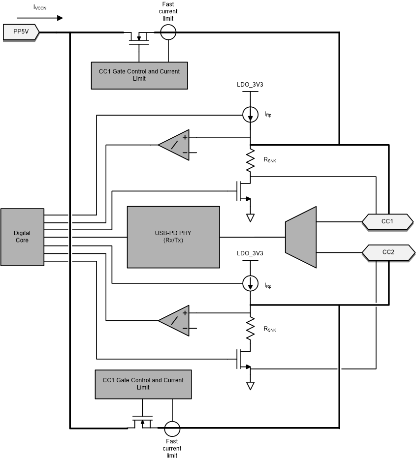
Figure 7-1 shows the USB PD physical layer block surrounded by a simplified version of the analog plug and orientation detection block.
 Figure 7-1 USB-PD Physical
Layer and Simplified Plug and Orientation Detection Circuitry
Figure 7-1 USB-PD Physical
Layer and Simplified Plug and Orientation Detection CircuitryUSB-PD messages are transmitted in a USB Type-C system using a BMC signaling. The BMC signal is output on the same pin (CC1 or CC2) that is DC biased due to the Rp (or Rd) cable attach mechanism.