SLVSDP3 December 2016 TPS54262-EP
PRODUCTION DATA.
- 1 Features
- 2 Applications
- 3 Description
- 4 Revision History
- 5 Pin Configuration and Functions
- 6 Specifications
-
7 Detailed Description
- 7.1 Overview
- 7.2 Functional Block Diagram
- 7.3
Feature Description
- 7.3.1 Unregulated Input Voltage
- 7.3.2 Regulated Output Voltage
- 7.3.3 Regulation and Feedback Voltage
- 7.3.4 Enable and Shutdown
- 7.3.5 Soft Start
- 7.3.6 Oscillator Frequency
- 7.3.7 Slew Rate Control
- 7.3.8 Reset
- 7.3.9 Reset Delay
- 7.3.10 Reset Threshold and Undervoltage Threshold
- 7.3.11 Overvoltage Supervisor
- 7.3.12 Noise Filter on RST_TH and OV_TH Terminals
- 7.3.13 Boot Capacitor
- 7.3.14 Short Circuit Protection
- 7.3.15 Overcurrent Protection
- 7.3.16 Internal Undervoltage Lockout (UVLO)
- 7.3.17 Thermal Shutdown (TSD)
- 7.3.18 Loop Control Frequency Compensation - Type 3
- 7.4 Device Functional Modes
-
8 Application and Implementation
- 8.1 Application Information
- 8.2
Typical Application
- 8.2.1 Design Requirements
- 8.2.2
Detailed Design Procedure
- 8.2.2.1
Component Selection
- 8.2.2.1.1 Input Capacitors (C1, C11)
- 8.2.2.1.2 Output Capacitor (C4, C12)
- 8.2.2.1.3 Soft-Start Capacitor (C6)
- 8.2.2.1.4 Bootstrap Capacitor (C3)
- 8.2.2.1.5 Power-On Reset Delay (PORdly) Capacitor (C2)
- 8.2.2.1.6 Output Inductor (L1)
- 8.2.2.1.7 Flyback Schottky Diode (D2)
- 8.2.2.1.8 Resistor to Set Slew Rate (R7)
- 8.2.2.1.9 Resistor to Select Switching Frequency (R8)
- 8.2.2.1.10 Resistors to Select Output Voltage (R4, R5)
- 8.2.2.1.11 Resistors to Set Undervoltage, Overvoltage, and Reset Thresholds (R1, R2, R3)
- 8.2.2.1.12 Low-Power Mode (LPM) Threshold
- 8.2.2.1.13 Enable Pin Pull-Up Resistor (R11) and Voltage Divider Resistor (R10)
- 8.2.2.1.14 Pull-Up Resistor (R12) at RST Pin
- 8.2.2.1.15 Type 3 Compensation Components (R5, R6, R9, C5, C7, C8)
- 8.2.2.1.16 Noise Filter on RST_TH and OV_TH Terminals (C9, C10)
- 8.2.2.2
Design Example 1
- 8.2.2.2.1 Calculate the Switching Frequency (fsw)
- 8.2.2.2.2 Calculate the Ripple Current (IRipple)
- 8.2.2.2.3 Calculate the Inductor Value (L1)
- 8.2.2.2.4 Calculate the Output Capacitor and ESR (C4)
- 8.2.2.2.5 Calculate the Feedback Resistors (R4, R5)
- 8.2.2.2.6 Calculate Type 3 Compensation Components
- 8.2.2.2.7 Calculate Soft-Start Capacitor (C6)
- 8.2.2.2.8 Calculate Bootstrap Capacitor (C3)
- 8.2.2.2.9 Calculate Power-On Reset Delay Capacitor (C2)
- 8.2.2.2.10 Calculate Input Capacitor (C1, C11)
- 8.2.2.2.11 Calculate Resistors to Control Slew Rate (R7)
- 8.2.2.2.12 Resistors to Select Undervoltage, Overvoltage and Reset Threshold Values (R1, R2, R3)
- 8.2.2.2.13 Diode D1 and D2 Selection
- 8.2.2.2.14 Noise Filter on RST_TH and OV_TH Terminals (C9 and C10)
- 8.2.2.2.15 Power Budget and Temperature Estimation
- 8.2.2.3
Design Example 2
- 8.2.2.3.1 Calculate the Switching Frequency (fsw)
- 8.2.2.3.2 Calculate the Ripple Current (IRipple)
- 8.2.2.3.3 Calculate the Inductor Value (L1)
- 8.2.2.3.4 Calculate the Output Capacitor and ESR (C4, C12)
- 8.2.2.3.5 Calculate the Feedback Resistors (R4, R5)
- 8.2.2.3.6 Calculate Type 3 Compensation Components
- 8.2.2.3.7 Calculate Soft-Start Capacitor (C6)
- 8.2.2.3.8 Calculate Bootstrap Capacitor (C3)
- 8.2.2.3.9 Calculate Power-On Reset Delay Capacitor (C2)
- 8.2.2.3.10 Calculate Input Capacitor (C1, C11)
- 8.2.2.3.11 Calculate Resistors to Control Slew Rate (R7)
- 8.2.2.3.12 Resistors to Select Undervoltage, Overvoltage and Reset Threshold Values (R1, R2, R3)
- 8.2.2.3.13 Diode D1 and D2 Selection
- 8.2.2.3.14 Noise Filter on RST_TH and OV_TH Terminals (C9 and C10)
- 8.2.2.3.15 Power Budget and Temperature Estimation
- 8.2.2.1
Component Selection
- 8.2.3 Application Curves
- 9 Power Supply Recommendations
- 10Layout
- 11Device and Documentation Support
- 12Mechanical, Packaging, and Orderable Information
Package Options
Mechanical Data (Package|Pins)
- PWP|20
Thermal pad, mechanical data (Package|Pins)
- PWP|20
Orderable Information
7 Detailed Description
7.1 Overview
The TPS54262-EP device is a 60-V, 2-A DC-DC step down (buck) converter using voltage-control mode scheme. The device features a supervisory function for power-on-reset during system power on. Once the output voltage has exceeded the threshold set by RST_TH pin, a delay of 1 ms/nF (based on capacitor value on Cdly terminal) is invoked before the RST line is released high. Conversely on power down, once the output voltage falls below the same set threshold, the RST line is pulled low only after a deglitch filter of approximately 20 µs (typical) expires. This is implemented to prevent reset from being triggered due to fast transient line noise on the regulated output supply.
An overvoltage monitor function is used to limit regulated output voltage to the threshold set by OV_TH pin. Both the RST_TH and OV_TH monitoring voltages are set to be a prescale of the output voltage, and thresholds based on the internal bias voltages of the voltage comparators (0.8-V typical).
Detection of undervoltage on the regulated output is based on the RST_TH setting and will invoke RST line to be asserted low. Detection of overvoltage on the output is based on the OV_TH setting and will not invoke the RST line to be asserted low. However, the internal switch is commanded to turn OFF.
In systems where power consumption is critical, low-power mode (LPM) is implemented to reduce the non-switching quiescent current during light-load conditions. After the device has been operating in discontinuous conduction mode (DCM) for at least 100 µs (typical), depending upon the load current, it may enter in pulse skip mode (PSM). The operation of when the device enters DCM is dependent on the selection of the external components.
If thermal shutdown is invoked due to excessive power dissipation, the internal switch is disabled and the regulated output voltage starts to decrease. Depending on the load current, the regulated output voltage could decay and the RST_TH threshold may assert the RST output low.
7.2 Functional Block Diagram
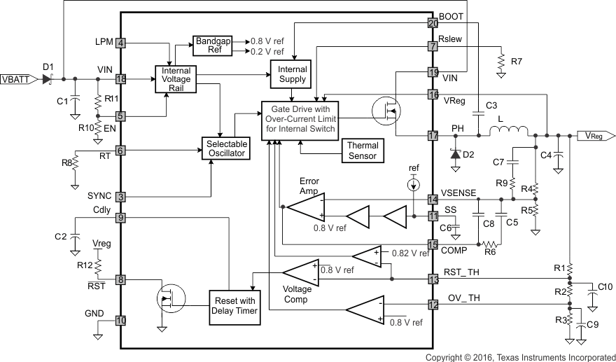
7.3 Feature Description
The TPS54262-EP device is a DC-DC converter using a voltage-control mode scheme with an input voltage feed-forward technique. The device can be programmed for a range of output voltages with a wide input voltage range. The following sections provide details regarding setting up the device, detailed functionality, and the modes of operation.
7.3.1 Unregulated Input Voltage
The input voltage is supplied through VIN pins (pin 18 and 19) which must be externally protected against voltage levels greater than 60 V and reverse input polarity. An external diode is connected to protect these pins from reverse input polarity. The input current drawn from this pin is pulsed, with fast rise and fall times. Therefore, this input line requires a filter capacitor to minimize noise. Additionally, for EMI considerations, an input filter inductor may also be required.
NOTE
For design considerations, VIN/VReg ratios should always be set such that the minimum required duty cycle pulse (tON-Min) is greater than 150 ns. The minimum off time (tOFF-Min) is 250 ns for all conditions.
7.3.2 Regulated Output Voltage
The regulated output voltage (VReg) is fed back to the device through VReg pin (pin 16). Typically, an output capacitor of value within range of 10 µF to 400 µF is connected at this pin. TI also recommends using a filter capacitor with low ESR characteristics to minimize ripple in regulated output voltage. The VReg pin is also internally connected to a load of approximately 100 Ω, which is turned ON in the following conditions:
- During start-up condition, when the device is powered up with no-load, or whenever EN is toggled, the internal load connected to VReg pin is turned ON to charge the bootstrap capacitor to provide gate drive voltage to the switching transistor.
- During normal operating conditions, when the regulated output voltage (VReg) exceeds the overvoltage threshold (VReg_OV, preset by external resistors R1, R2, and R3), the internal load is turned ON, and this pin is pulled down to bring the regulated output voltage down.
- When VIN is less than typical VIN falling threshold level while LPM is disabled. From device specifications, VIN typical falling threshold (LPM disabled) = 8 V (see DC Electrical Characteristics).
- When RST is low.
7.3.3 Regulation and Feedback Voltage
The regulated output voltage (VReg) can be programmed by connecting external resistor network at VSENSE pin (pin 14). The output voltage is selectable from 0.9 V to 18 V according to the following relationship:
The overall tolerance of the regulated output voltage is given by Equation 2.

where
- tolVref = tolerance of internal reference voltage (tolVref = ± 1.5%)
- tolR4,tolR5 = tolerance of feedback resistors R4, R5
For a tighter tolerance on VReg, lower-value feedback resistors can be selected. However, for proper operation in low-power mode (see Figure 17), TI recommends keeping R4 + R5 around 250 kΩ (typical).
The output tracking depends upon the loading conditions and is explained in Table 1 and is shown in Figure 6.
Table 1. Load Conditions
| LOAD CONDITION | OUTPUT TRACKING |
|---|---|
| Nominal load in CCM | VReg tracks VIN approximately as: VReg = 95% (VIN – ILoad × 0.5) |
| No load/light load in LPM | To enable the tracking feature, following conditions should be met: 1) fSW < 600 kHz 2) VReg < 8 V, typical (related to VIN falling threshold when LPM is disabled) |
7.3.4 Enable and Shutdown
The EN pin (pin 5) provides electrical ON/OFF control of the regulator. Once the EN pin voltage exceeds the upper threshold voltage (VIH), the regulator starts operating and the internal soft start begins to ramp. If the EN pin voltage is pulled below the lower threshold voltage (VIL), the regulator stops switching and the internal soft start resets. Connecting this pin to ground or to any voltage less than VIL disables the regulator and causes the device to shut down. This pin must have an external pullup or pulldown to change the state of the device.
7.3.5 Soft Start
An external soft-start capacitor is connected to SS pin (pin 11) to set the minimum time to reach the desired regulated output voltage (VReg) during power-up cycle. This prevents the output voltage from overshooting when the device is powered up. This is also useful when the load requires a controlled voltage slew rate, and also helps to limit the current drawn from the input voltage supply line.
For proper operation, the following conditions must be satisfied during power up and after a short circuit event:
- VIN – VReg > 2.5 V
- Load current < 1 A, until RST goes high
The power-up current limit (30% of the typical current limit value) is released after the feedback voltage (at VSENSE pin) is high enough such that RST is asserted high. The recommended value of soft-start capacitor is 100 nF (typical) for start-up load current of 1 A (maximum).
7.3.6 Oscillator Frequency
The oscillator frequency can be set by connecting an external resistor (R8 in Functional Block Diagram) to RT pin (pin 6). Figure 10 shows the relation between the resistor value (RT) and switching frequency (fsw). The switching frequency can be set in the range 200 kHz to 2200 kHz. In addition, the switching frequency can be imposed externally by a clock signal (fext) at the SYNC pin.
7.3.6.1 Selecting the Switching Frequency
A power supply switching at a higher switching frequency allows use of lower value inductor and smaller output capacitor compared to a power supply that switches at a lower frequency. Typically, the user will want to choose the highest switching frequency possible because this will produce the smallest solution size. The switching frequency that can be selected is limited by the following factors:
- The input voltage
- The minimum target regulated voltage
- Minimum on-time of the internal switching transistor
- Frequency shift limitation
Selecting lower switching frequency results in using an inductor and capacitor of a larger value, where as selecting higher switching frequency results in higher switching and gate drive power losses. Therefore, a tradeoff must be made between physical size of the power supply and the power dissipation at the system/ application level.
The minimum and maximum duty cycles can be expressed in terms of input and output voltage as shown in Equation 3.

where
- DMin = minimum duty cycle
- DMax = maximum duty cycle
- VINMin = minimum input voltage
- VINMax = maximum input voltage
- VReg-Min = minimum regulated output voltage
- VReg-Max = maximum regulated output voltage
Maximum switching frequency can be calculated using Equation 4.

where
- fsw-Max = maximum switching frequency
- tON-Min = minimum on-time of the NMOS switching transistor
Knowing the switching frequency, the value of resistor to be connected at RT pin can be calculated using the graph shown in Figure 10. Consider the oscillator tolerance (±10%) while selecting the external RT resistor. For example if fsw = 2.2 MHz is required, select the RT resistor which corresponds to fsw = 2 MHz in Figure 10 to allow +10% oscillator tolerance.
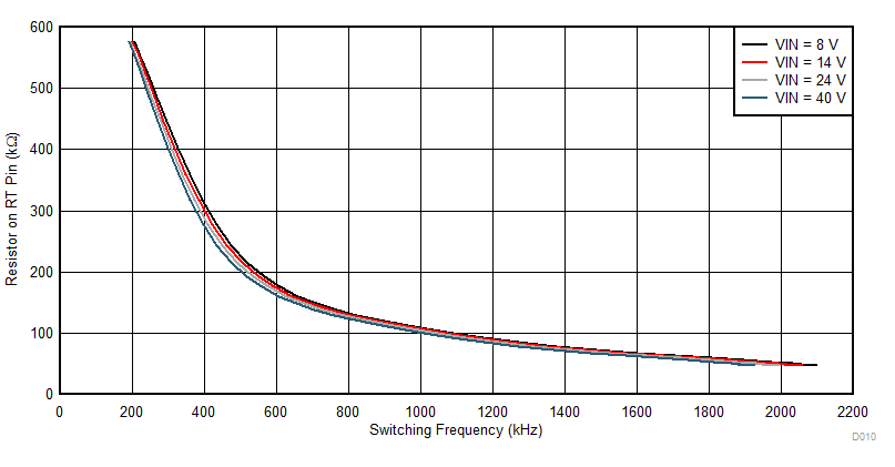 Figure 10. Switching Frequency vs Resistor Value
7.3.6.2 Synchronization With External Clock
An external clock signal can be supplied to the device through SYNC pin (pin 3) to synchronize the internal oscillator frequency with an external clock frequency. The synchronization input overrides the internal fixed oscillator signal. The synchronization signal must be valid for approximately two clock cycles before the transition is made for synchronization with the external frequency input. If the external clock input does not transition low or high for 32 µs (typical), the system defaults to the internal clock set by the resistor connected to the RT pin. The SYNC input can have a frequency according to Equation 5.
where
- fsw = oscillator frequency determined by resistor connected to the RT pin
- fext = frequency of the external clock fed through SYNC pin
For example, if the resistor connected at RT pin is selected such that the switching frequency (fsw) is 500 kHz, then the external clock can have a frequency (fext) from 500 kHz to 1000 kHz. But, if the resistor connected at RT pin is selected such that the switching frequency (fsw) is 1500 kHz, then the external clock can have a frequency (fext) from 1500 kHz to 2200 kHz only.
If the external clock goes off for less than 32 µs, the NMOS switching FET is turned off and the output voltage starts decreasing. Depending upon the load conditions, the output voltage may hit the undervoltage threshold and reset threshold before the external clock appears. The NMOS switching FET stays OFF until the external clock appears again. If the output voltage hits the reset threshold, the RST pin is asserted low after a deglitch time of 20 µs (typical).
If the external clock goes off for more than 32 µs, the NMOS switching FET is turned off and the output voltage starts decreasing. Under this condition the default internal oscillator clock set by RT pin overrides the external after 32 µs and the NMOS switching FET resumes switching. When the external clock appears again (such that 180 kHz < fsw < fext < 2 × fsw < 2.2 MHz), the NMOS switching FET starts switching at the frequency determined by the external clock.
7.3.7 Slew Rate Control
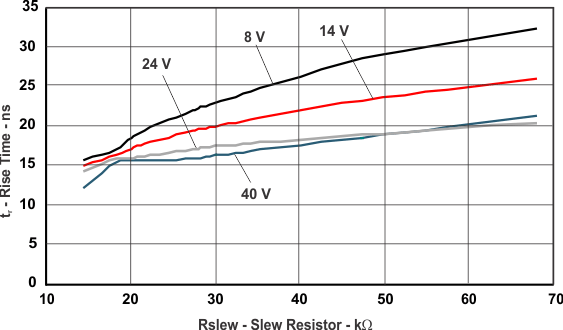
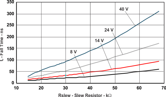
The slew rate of the NMOS switching FET can be set by using an external resistor (R7 in Functional Block Diagram). The range of rise times and fall times for different values of slew resistor are shown in Figure 11 and Figure 12.
7.3.8 Reset
The RST pin (pin 8) is an open-drain output pin used to indicate external digital devices and loads if the device has powered up to a programmed regulated output voltage properly. This pin is asserted low until the regulated output voltage (VReg) exceeds the programed reset threshold (VREG_RST, see Equation 8) and the reset delay timer (set by Cdly pin) has expired. Additionally, whenever the EN pin is low or open, RST is immediately asserted low regardless of the output voltage. There is a reset filter timer to prevent reset being invoked due to short negative transients on the output line. If thermal shutdown occurs due to excessive thermal conditions, this pin is asserted low when the switching FET is commanded OFF and the output falls below the reset threshold.
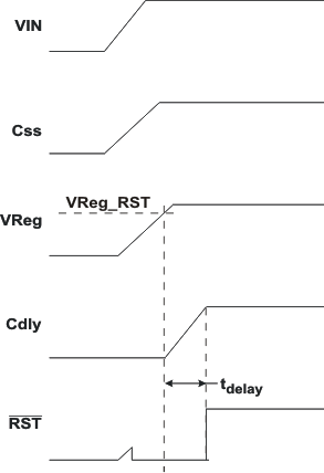 Figure 13. Power-On Condition and Reset Line
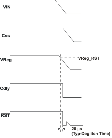 Figure 14. Power-Down Condition and Reset Line
7.3.9 Reset Delay
The delay time to assert the RST pin high after the supply has exceeded the programmed VReg_RST voltage (see Equation 8 to calculate VReg_RST) can be set by external capacitor (C2 in Functional Block Diagram) connected to the Cdly pin (pin 9). The delay may be programmed in the range of 2.2 ms to 200 ms using a capacitor in the range of 2.2 nF to 200 nF. The delay time is calculated using Equation 6:

where
- C = capacitor on Cdly pin
7.3.10 Reset Threshold and Undervoltage Threshold
The undervoltage threshold (VReg_UV) level for proper regulation in low-power mode and the reset threshold level (VReg_RST) to initiate a reset output signal can be programmed by connecting an external resistor string to the RST_TH pin (pin 13). The resistor combination of R1, R2, and R3 is used to program the threshold for detection of undervoltage. Voltage bias on R2 + R3 sets the reset threshold.
Undervoltage threshold for transient and low-power mode operation is given by the Equation 7. The recommended range for VReg_UV is 73% to 95% of VReg.

Reset threshold is given by Equation 8. The recommended range for VReg_RST is 70% to 92% of VReg.

7.3.11 Overvoltage Supervisor
The overvoltage monitoring of the regulated output voltage, VReg can be achieved by connecting an external resistor string to the OV_TH pin (pin 12). The resistor combination of R1, R2, and R3 is used to program the threshold for detection of overvoltage. The bias voltage of R3 sets the overvoltage threshold and the accuracy of regulated output voltage in hysteretic mode during transient events.

Recommended range for VReg_OV is 106% to 110% of VReg.
7.3.12 Noise Filter on RST_TH and OV_TH Terminals
External capacitors may be required to filter the noise added to RST_TH and OV_TH terminals. The noise is more pronounced with fast falling edges on the PH pin. Therefore, selecting a smaller Rslew resistor (R7 in Functional Block Diagram) for a higher slew rate will require more external capacitance to filter the noise.
The RC time constant depends on external components (R2, R3, C9 and C10 in Functional Block Diagram) connected to RST_TH and OV_TH pins. For proper noise filtering, improved loop transient response and better short circuit protection, Equation 10 must be satisfied.
To meet this requirement, TI recommends to use lower values of external capacitors and resistors. The value of the time constant is also affected by the PCB capacitance and the application setup. Therefore, in some cases the external capacitors (C9, C10) on RST_TH and OV_TH terminals may not be required. Users can place a footprint on the application PCB and only populate it if necessary. Also, the external resistors (R1, R2, R3) must be sized appropriately to minimize any significant effect of board leakage.
For most cases, TI recommends keeping the external capacitors (either from board capacitance or by connecting external capacitors) between 10 pF to 100 pF; therefore, to meet time constant requirement in Equation 10, the total external resistance (R1 + R2 + R3) should be less than 200 kΩ.
7.3.13 Boot Capacitor
An external boot strap capacitor (C3 in Functional Block Diagram) is connected to pin 20 (BOOT) to provide the gate drive voltage for the internal NMOS switching FET. TI recommends X7R or X5R grade dielectrics because of their stable values over temperature. The capacitor value may need to be adjusted higher for high VReg and/or low frequencies applications (for example, 100 nF for 500 kHz/5 V and 220 nF for 500 kHz/8 V).
7.3.14 Short Circuit Protection
The TPS54262-EP features an output short circuit protection. Short circuit conditions are detected by monitoring the RST_TH pin, and when the voltage on this node drops below 0.2 V, the switching frequency is decreased and current limit is folded back to protect the device. The switching frequency is folded back to approximately 25 kHz and the current limit is reduced to 30% of the typical current limit value.
7.3.15 Overcurrent Protection
The device features overcurrent protection to protect it from load currents greater than 2 A. Overcurrent protection is implemented by sensing the current through the NMOS switching FET. The sensed current is compared to a current reference level representing the overcurrent threshold limit (ICL). If the sensed current exceeds the overcurrent threshold limit, the overcurrent indicator is set true. The system will ignore the overcurrent indicator for the leading edge blanking time at the beginning of each cycle to avoid any turnon noise glitches.
Once overcurrent indicator is set true, overcurrent protection is triggered. The NMOS switching FET is turned off for the rest of the cycle after a propagation delay. The overcurrent protection scheme is called cycle-by-cycle current limiting. If the sensed current continues to increase during cycle-by-cycle current limiting, the temperature of the part will start rising, the TSD will kick in and shutdown switching until the part cools down.
7.3.16 Internal Undervoltage Lockout (UVLO)
This device is enabled on power up once the internal bandgap and bias currents are stable; this happens typically at VIN = 3.4 V (minimum). On power down, the internal circuitry is disabled at VIN = 2.6 V (maximum).
7.3.17 Thermal Shutdown (TSD)
The TPS54262-EP protects itself from overheating with an internal thermal shutdown (TSD) circuit. If the junction temperature exceeds the thermal shutdown trip point, the NMOS switching FET is turned off. The device is automatically restarted under the control of soft-start circuit when the junction temperature drops below the thermal shutdown hysteretic trip point. During low-power mode operation, the thermal shutdown sensing circuitry is disabled for reduced current consumption. If VReg drops below VReg_UV, thermal shutdown monitoring is activated.
7.3.18 Loop Control Frequency Compensation – Type 3
Type 3 compensation has been used in the feedback loop to improve the stability of the convertor and regulation in the output in response to the changes in input voltage or load conditions. This becomes important because the ceramic capacitors used to filter the output have a low Equivalent Series Resistance (ESR). Type 3 compensation is implemented by connecting external resistors and capacitors to the COMP pin (output of the error amplifier, pin 15) of the device as shown in Figure 15.
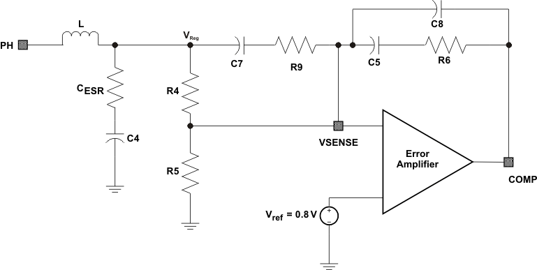 Figure 15. Type 3 Compensation
The crossover frequency should be less than 1/5th to 1/10th of the switching frequency, and should be greater than five times the double pole frequency of the LC filter.
where
- fsw = switching frequency
The modulator break frequencies as a function of the output LC filter are derived from Equation 12 and Equation 13. The LC output filter gives a double pole that has a –180° phase shift.

where
- L = output inductor
- C = output capacitor (C4 in functional block diagram)
The ESR of the output capacitor C gives a ZERO that has a 90° phase shift.

where
- ESR = Equivalent series resistance of a capacitor at a specified frequency
The regulated output voltage, VReg is given by Equation 14.


For VIN = 8 V to 50 V, the VIN/Vramp modulator gain is approximately 10 and has a tolerance of about 20%.

Therefore,

Also, Vramp is fixed for the following range of VIN. Vramp = 1 V for VIN < 8 V, and Vramp = 5 V for VIN > 48 V.
The frequencies for poles and zeros are given by following equations.


Guidelines for selecting compensation components selection are provided in the Application and Implementation section of this document.
7.3.18.1 Bode Plot of Converter Gain
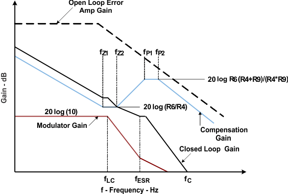 Figure 16. Bode Plot of Converter Gain Plot
7.4 Device Functional Modes
TPS54262-EP operates in the following modes based on the output loading conditions, input voltage, and LPM pin configuration. These operating conditions and modes of operations are shown in Figure 17.
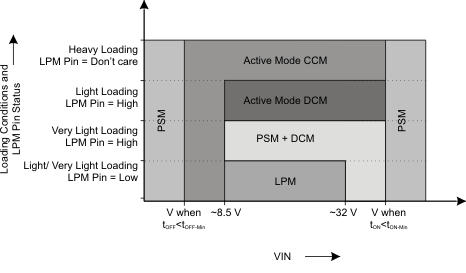 Figure 17. Modes of Operation
7.4.1 Active Mode Continuous Conduction Mode (CCM)
In this mode of operation the switcher operates in continuous conduction mode, and the inductor current is always non-zero if the total load current (internal and external) is greater than IL_DISCONT shown in Equation 22.

where
- D = duty cycle
- L = output inductor
- VReg = output voltage
- fsw = switching frequency
For VIN < 8.5 V, the device enables an internal approximately 100-Ω load. This, combined with the external load, can cause the device to enter into CCM even under light external loading conditions (see Device Functional Modes). This mode of operation is shown in Figure 18 is also called the Normal mode of operation.
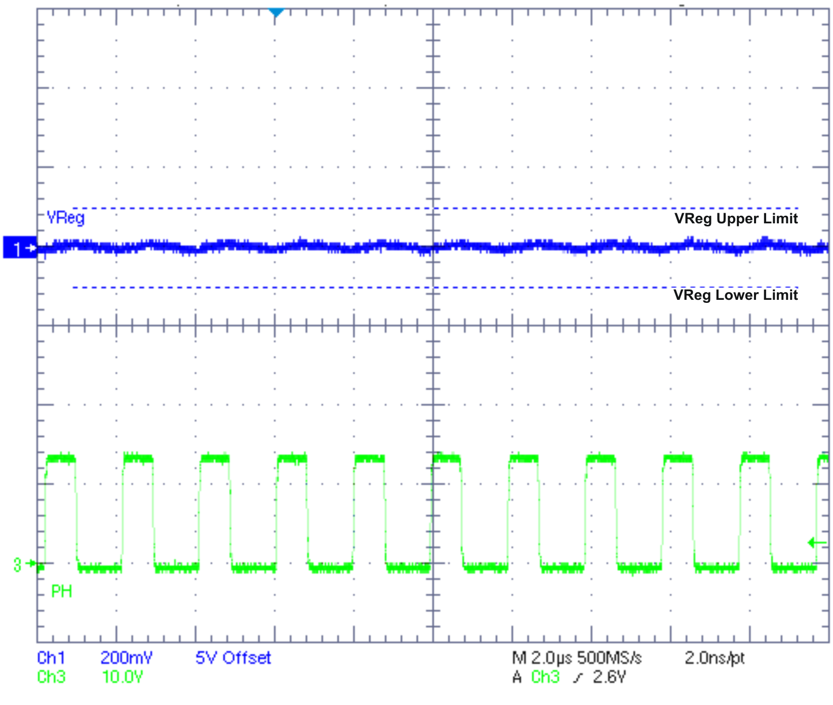
| VIN = 14 V | ILoad = 1 A | fsw = 500 kHz |
| LPM pin = don't care |
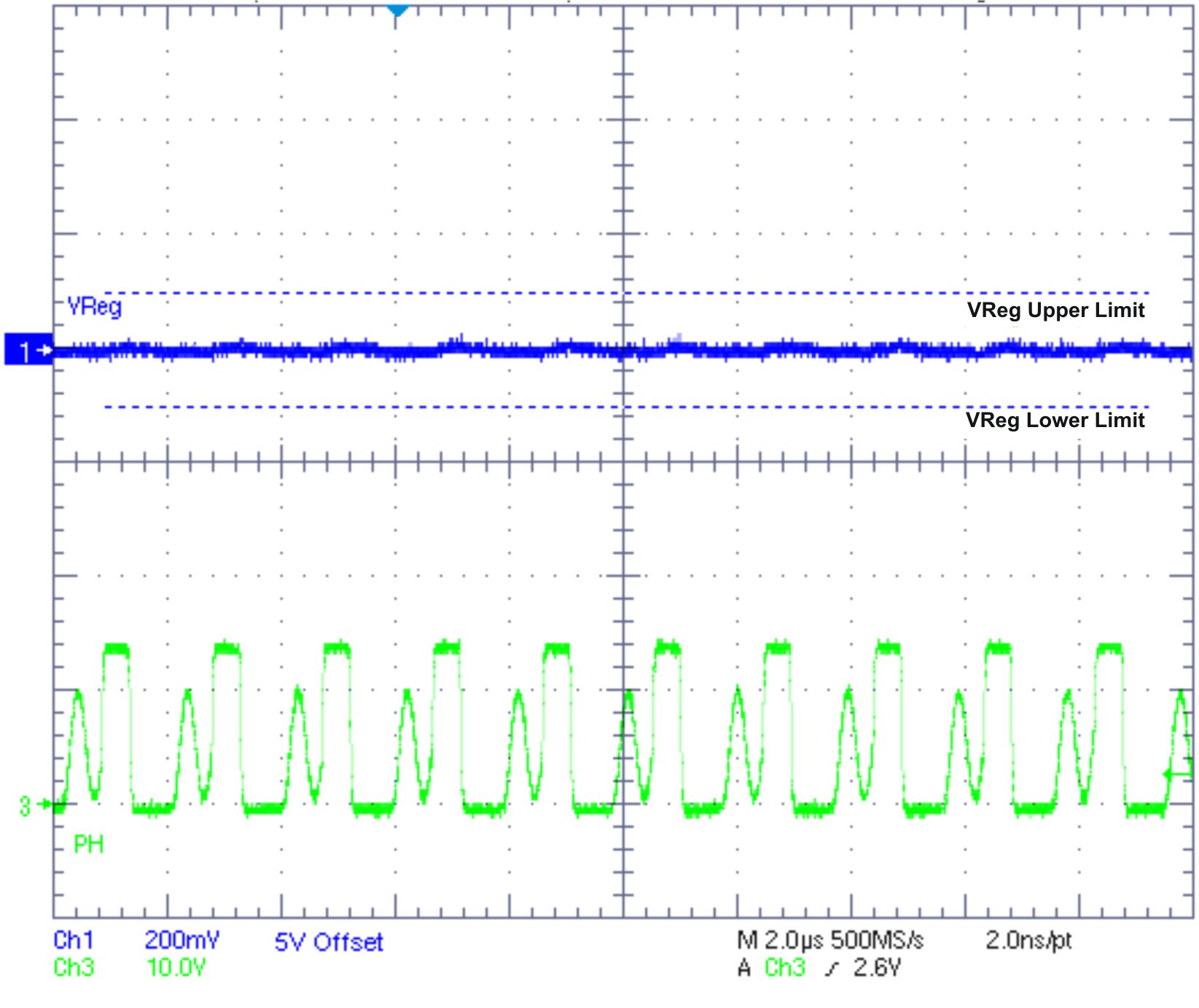
| VIN = 14 V | ILoad = 55 mA | fsw = 500 kHz |
| LPM pin = disable |
7.4.2 Active Mode Discontinuous Conduction Mode (DCM)
In this mode of operation the switcher operates in discontinuous conduction mode, and the inductor current becomes zero if the total load current (internal and external) is less than IL_DISCONT shown in Equation 23.

The device enters in this mode of operation when LPM pin is set high (disabled) and output loading is less than IL_DISCONT. This mode of operation is shown in Figure 19.
7.4.3 Pulse Skip Mode (PSM)
In this mode of operation the switcher operates in discontinuous conduction mode, and the inductor current becomes zero. The device enters in this mode of operation in the following conditions:
- At low input voltages when VReg starts losing regulation and the OFF time (tOFF) of the switching FET tends to be close to or slightly less than the minimum OFF time (tOFF-Min). If OFF time is much smaller than tOFF-Min, there is a risk that the part stops switching and regulation is lost until power is re-cycled with OFF time greater than tOFF-Min. This mode of operation is shown in Figure 21. Comparing Figure 20 and Figure 21, pulse skipping occurs in Figure 21 but not in Figure 20 under similar output loading conditions.

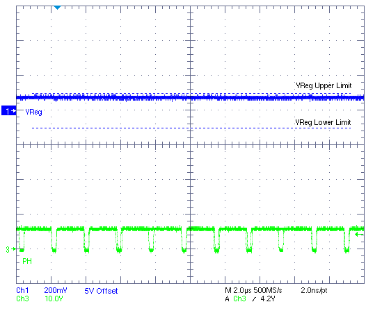
| VIN = 6.2 V | ILoad = 50 mA | fsw = 500 kHz |
| LPM pin = don't care |
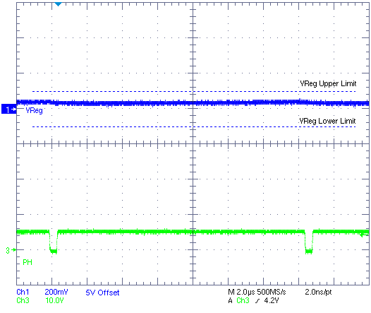
| VIN = 5.5 V | ILoad = 50 mA | fsw = 500 kHz |
| LPM pin = don't care |
- Likewise, at higher input voltages when the ON time (tON) of the switching FET becomes close to or slightly less than the minimum ON time (tON-Min) and the VReg start losing regulation, the device enters in PSM. If ON time is much smaller than tON-Min, there is a risk that the part stops switching and regulation is lost until power is recycled with ON time greater than tON-Min.
- At nominal input voltages during very light output loading. This mode of operation is shown in Figure 22. Comparing Figure 19 and Figure 22, in both cases the device is operating in discontinuous conduction mode; however, pulse skipping happens in Figure 22 because of very light output loading for similar input voltage. LPM pin must be set high (disabled) for this to happen.
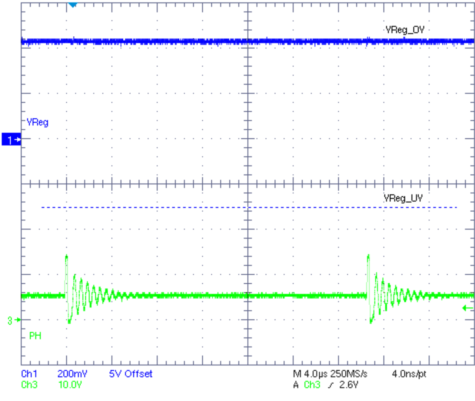
| VIN = 14 V | ILoad = 50 µA | fsw = 500 kHz |
| LPM pin = disable |
7.4.4 Low-Power Mode (LPM)
In this mode of operation the device briefly operates in discontinuous conduction mode and then turns off until VReg < VReg_UV threshold and this cycle is repeated. The LPM pin must be enabled to enable LPM mode of operation. When total load is less than IL_DISCONT, the device operates in LPM for VIN approximately 8.5 V to approximately 32 V. This mode of operation is shown in Figure 23 and Figure 24 (zoomed out).
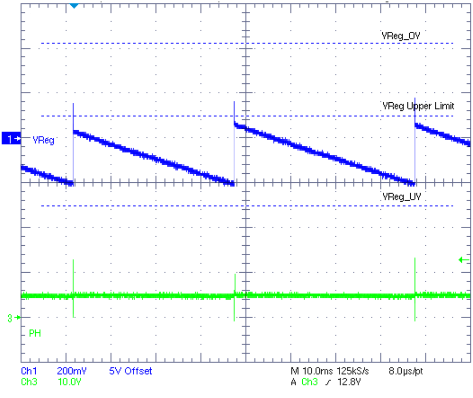
| VIN = 14 V | ILoad = 50 mA | fsw = 500 kHz |
| LPM pin = enable |
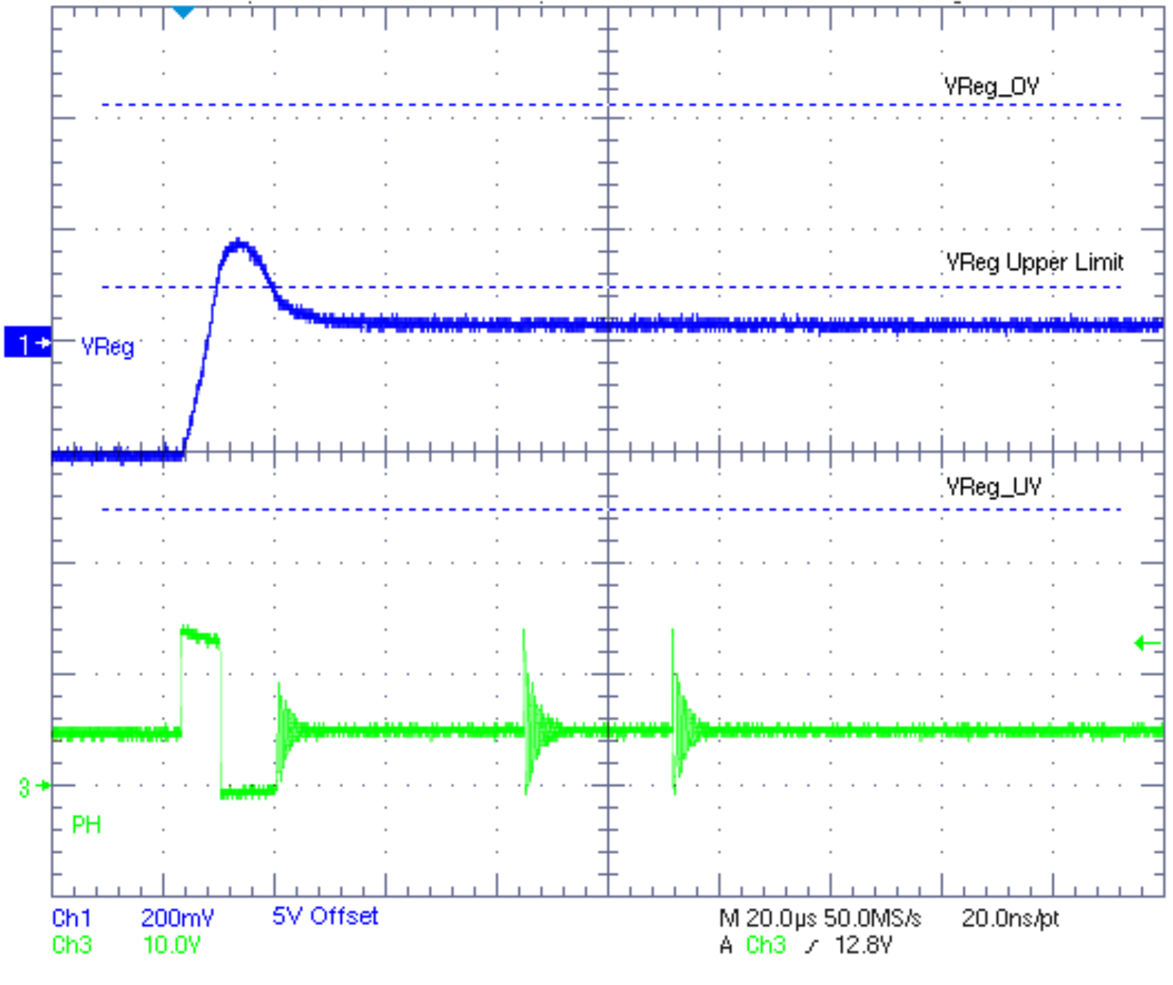
| VIN = 14 V | ILoad = 50 mA | fsw = 500 kHz |
| LPM pin = enable |
Any transition from low-power mode to active mode CCM occurs within 5 µs (typical). In low-power mode, the converter operates as a hysteretic controller with the threshold limits set by VReg_UV (see Equation 7, Functional Block Diagram and Figure 25), for the lower limit and approximately VReg for the upper limit. To ensure tight regulation in the low-power mode, R2 and R3 values are set accordingly (see discussion on Noise Filter on RST_TH and OV_TH Terminals). The device operates in both automatic (LPM pin is connected to ground) and digitally controlled (status of LPM pin is controlled by an external device, for example by a microcontroller) low-power mode. The digital low-power mode can over-ride the automatic low-power mode function by applying the appropriate signal on the LPM terminal. The part goes into active mode CCM for at least 100 µs, whenever RST_TH or VReg_UV is tripped.
Table 2. LPM Pin Status
| LPM PIN STATUS | MODES OF OPERATION |
|---|---|
| High | Device is forced in normal mode. |
| At light loads, the device operates in DCM with a switching frequency determined by the external resistor connected to RT pin. | |
| At very light loads, the device operates in PSM with a reduced switching frequency (see Figure 17). | |
| Low or open | Device automatically changes between normal mode and low-power mode depending on the load current. |
Table 3. Modes of Operation
| MODES OF OPERATION | DESCRIPTION |
|---|---|
| Normal mode (active mode) | All circuits including overvoltage threshold circuit (OV_TH) are enabled. |
| At heavy loads, the device operates in continuous conduction mode irrespective of the status of LPM pin. OR At light loads, the device operates in discontinuous conduction mode (DCM) only if LPM pin is externally set high. |
|
| Low-power mode | OV_TH circuit is disabled. The device is in DCM, and LPM pin should be forced low. |
When the device is operating in low-power mode, and if the output is shorted to ground, a reset is asserted. The thermal shutdown and current limiting circuitry is activated to protect the device. The LPM pin is active low and is internally pulled down; therefore, the low-power mode is automatically enabled unless this pin is driven high externally (for example, by a microcontroller) and the device is in continuous conduction mode. However, the low-power mode operation is initiated only when the device enters discontinuous mode of operation at light loads, and the LPM pin is low (or connected to ground).
7.4.5 Hysteretic Mode
The device enters in this mode of operation when the main loop fails to respond during line and load transients and regulate within specified tolerances. The device exits this mode of operation when the main control loop responds, after the error amplifier stabilizes, and controls the output voltage within tighter tolerance.
The power up conditions in different modes of operations are explained in Table 4.
Table 4. Power-Up Conditions
| MODE OF OPERATION | POWER-UP CONDITIONS |
|---|---|
| CCM | VIN > 3.6 V (minimum) |
| LPM/DCM | VReg < 5.5 V and (VIN – VReg) > 2.5 V (applicable only for fsw > 600 kHz) |
7.4.6 Output Tolerances in Different Modes of Operation
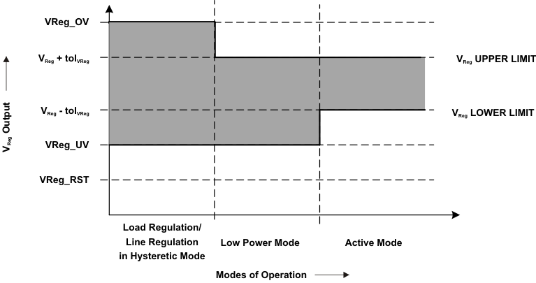 Figure 25. Output Tolerances Diagram
Table 5. Mode of Operation Descriptions
| MODE OF OPERATION | VReg LOWER LIMIT | VReg UPPER LIMIT | COMMENTS |
|---|---|---|---|
| Hysteretic mode | VReg_UV | VReg_OV | Minimum to maximum ripple on output |
| Low-power mode | VReg_UV | VReg + tolVReg | Minimum to maximum ripple on output |
| Active mode (Normal) | VReg – tolVReg | VReg + tolVReg | Minimum to maximum ripple on output |
Table 6. Supervisor Thresholds Descriptions
| SUPERVISOR THRESHOLDS | VReg TYPICAL VALUE | TOLERANCE | COMMENTS |
|---|---|---|---|
| VReg_OV |  |
 |
Overvoltage threshold setting |
| VReg_RST |  |
 |
Reset threshold setting |
