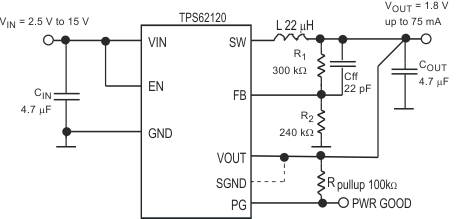
The TPS6212x device is a highly efficient synchronous step-down DC-DC converter optimized for low-power applications. The device supports up to 75-mA output current and allows the use of tiny external inductors and capacitors.
The wide operating input voltage range of 2 V to 15 V supports energy harvesting, battery powered and as well 9-V or 12-V line powered applications.
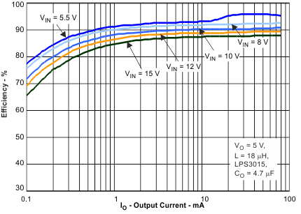
With its advanced hysteretic control scheme, the converter provides power save mode operation. At light loads the converter operates in pulse frequency modulation (PFM) mode and transitions automatically in pulse width modulation (PWM) mode at higher load currents. The power save mode maintains high efficiency over the entire load current range. The hysteretic control scheme is optimized for low output ripple voltage in PFM mode in order to reduce output noise to a minimum. The device consumes only 10-µA quiescent current from VIN in PFM mode operation.
In shutdown mode, the device is turned off.
An open-drain power good output is available in the TPS62120 and indicates once the output voltage is in regulation.
The TPS62120 has an additional SGND pin which is connected to GND during shutdown mode. This output can be used to discharge the output capacitor.
The TPS6212x operates over an free air temperature range of –40°C to 85°C. The TPS62120 is available in a small 8-pin SOT-23 package and the TPS62122 in a 2 mm × 2 mm 6-pin DFN package.
PART NUMBER | PACKAGE | BODY SIZE (NOM) |
---|---|---|
TPS62120 | SOT-23 (8) | 2.90 mm × 1.63 mm |
TPS62122 | SON (6) | 2.00 mm × 2.00 mm |
Changes from * Revision (July 2010) to A Revision
PART NUMBER | ACTIVE DISCHARGE SWITCH | POWER GOOD | VOUT |
---|---|---|---|
TPS62120(1) | yes | Open-Drain | adjustable |
TPS62122(2) | no | no | adjustable |
PIN | I/O | DESCRIPTION | ||
---|---|---|---|---|
NAME | DFN | SOT-23 | ||
EN | 4 | 3 | I | Pulling this pin to high activates the device. Low level shuts it down. This pin must be terminated. |
FB | 3 | 5 | I | This is the feedback pin for the regulator. Connect external resistor-divider to this pin. |
GND | 6 | 2 | PWR | GND supply pin. |
PG | — | 6 | O | This pin is available in TPS62120 only. Open-drain power good output. Connect this terminal through a pullup resistor to a voltage rail up to 5.5 V or leave it open. This pin can sink 500 µA. |
SGND | — | 4 | I | This pin is available in TPS62120 only. Open-drain output which is turned on during shutdown mode (EN = 0) or VIN is below the UVLO threshold. The output connects the SGND pin to GND through an internal MOSFET with typical 370-Ω RDS(ON). When the device is enabled (EN = 1), this output is high impedance. To discharge the output capacitor during shutdown mode, connect this pin to VOUT (output capacitor) or leave it open. |
SW | 1 | 7 | O | This is the switch pin and is connected to the internal MOSFET switches. Connect the inductor to this terminal. Do not tie this pin to VIN, VOUT or GND. |
VIN | 5 | 1 | PWR | VIN power supply pin. |
VOUT | 2 | 8 | I | This pin must be connected to the output capacitor. |
— | Exposed Thermal Pad | — | — | Exposed thermal pad available only in DRV package option. This pad must be connected to GND. |
MIN | MAX | UNIT | |||
---|---|---|---|---|---|
VI | Voltage at VIN(2) | –0.3 | 17 | V | |
Voltage at SW PIN | dynamically during switching t < 10 µs | 17 | V | ||
static DC | –0.3 | 6 | |||
Voltage at EN PIN(2) | –0.3 | VIN +0.3, but ≤17 | V | ||
Voltage on FB Pin | –0.3 | 3.6 | V | ||
Voltage at PG, VOUT, SGND(2) | –0.3 | 6 | V | ||
IIN | Current into PG pin | 0.5 | mA | ||
Maximum operating junction temperature, TJ | –40 | 125 | °C | ||
Storage temperature, Tstg | –65 | 150 | °C |
VALUE | UNIT | ||||
---|---|---|---|---|---|
V(ESD) | Electrostatic discharge | Human body model (HBM), per ANSI/ESDA/JEDEC JS-001(1) | ±2000 | V | |
Charged device model (CDM), per JEDEC specification JESD22-C101(2) | ±1000 |
MIN | NOM | MAX | UNIT | ||
---|---|---|---|---|---|
Supply voltage VIN, device in operation | 2 | 15 | V | ||
Output current capability | VIN = 2 V, VOUT = 1.8 V, DCRL = 0.7 Ω | 25 | mA | ||
VIN ≥ 2.5 V, VOUT = 1.8 V, DCRL = 0.7 Ω | 75 | ||||
Effective inductance | 10 | 22 | 33 | µH | |
Effective output capacitance | 1.0 | 2 | 33 | µF | |
Output voltage | 1.2 | 5.5 | V | ||
Operating ambient temperature TA(1), (unless otherwise noted) | –40 | 85 | °C | ||
Operating junction temperature, TJ | –40 | 125 | °C |
THERMAL METRIC(1) | TPS62120 | TPS62122 | UNIT | |
---|---|---|---|---|
DCN [SOT-23] | DRV [DFN] | |||
8 PINS | 6 PINS | |||
RθJA | Junction-to-ambient thermal resistance | 259.7 | 114.4 | °C/W |
RθJC(top) | Junction-to-case(top) thermal resistance | 114.1 | 73.7 | °C/W |
RθJB | Junction-to-board thermal resistance | 185.8 | 201.9 | °C/W |
ψJT | Junction-to-top characterization parameter | 21.6 | 0.8 | °C/W |
ψJB | Junction-to-board characterization parameter | 121.6 | 94.9 | °C/W |
RθJC(bot) | Junction-to-case(bottom) thermal resistance | n/a | 122.7 | °C/W |
PARAMETER | TEST CONDITIONS | MIN | TYP | MAX | UNIT | |
---|---|---|---|---|---|---|
SUPPLY | ||||||
VIN | Input voltage range(1) | Device operating | 2 | 15 | V | |
IQ | Quiescent current | IOUT = 0 mA, device not switching, EN = VIN, regulator sleeps | 11 | 18 | µA | |
IOUT = 0 mA, device switching, VIN = 8 V, VOUT = 1.8 V | 13 | |||||
IActive | Active mode current consumption | VIN = 5.5 V = VOUT, TJ = 25°C, high-side MOSFET switch fully turned on | 240 | 275 | µA | |
ISD | Shutdown current | EN = GND, VOUT = SW = 0 V, VIN = 3.6 V (2) | 0.3 | 1.2 | µA | |
VUVLO | Undervoltage lockout threshold | Falling VIN | 1.85 | 1.95 | V | |
Rising VIN | 2.5 | 2.61 | ||||
ENABLE, THRESHOLD | ||||||
VIH TH | Threshold for detecting high EN | 2 V ≤ VIN ≤ 15 V, rising edge | 0.8 | 1.1 | V | |
VIL TH HYS | Threshold for detecting low EN | 2 V ≤ VIN ≤ 15 V, falling edge | 0.4 | 0.6 | V | |
IIN | Input bias current, EN | EN = GND or VIN | 0 | 50 | nA | |
POWER SWITCH | ||||||
RDS(ON) | High-side MOSFET ON-resistance | VIN = 3.6 V | 2.3 | 3.4 | Ω | |
VIN = 8 V | 1.75 | 2.5 | ||||
Low-side MOSFET ON-resistance | VIN = 3.6 V | 1.3 | 2.5 | |||
VIN = 8 V | 1.2 | 1.75 | ||||
ILIMF | Forward current limit MOSFET high-side | VIN = 8 V, open loop | 200 | 250 | 400 | mA |
TSD | Thermal shutdown | Increasing junction temperature | 150 | °C | ||
Thermal shutdown hysteresis | Decreasing junction temperature | 20 | °C | |||
REGULATOR | ||||||
tONmin | Minimum ON time | VIN = 3.6 V, VOUT = 1.8 V | 700 | ns | ||
tOFFmin | Minimum OFF time | VIN = 3.6 V, VOUT = 1.8 V | 60 | ns | ||
VREF | Internal reference voltage | 0.8 | V | |||
VFB | Feedback FB voltage comparator threshold | Referred to 0.8-V internal reference | –2.5% | 0% | 2.5% | |
Feedback FB voltage line regulation | IOUT = 50 mA (4) | 0.04 | %/V | |||
IIN | Input bias current FB | VFB = 0.8 V | 0 | 50 | nA | |
tStart | Regulator start-up time | Time from active EN to device starts switching, VIN = 2.6 V | 50 | 150 | µs | |
tRamp | Output voltage ramp time | Time to ramp up VOUT = 1.8 V, no load (3) | 120 | 300 | ||
ILK_SW | Leakage current into SW pin | VOUT = VIN = VSW = 1.8 V, EN = GND, device in shutdown mode | 1 | 1.5 | µA | |
POWER GOOD OUTPUT (TPS62120) | ||||||
VTHPG | Power good threshold voltage | Rising VFB feedback voltage | 93% | 95% | 97% | |
Falling VFB feedback voltage | 87% | 90% | 93% | |||
VOL | Output low voltage | Current into PG pin I = 500 µA, VOUT > 1.5 V | 165 | mV | ||
Current into PG pin I = 100 µA, 1.2 V < VOUT < 1.5 V | 50 | |||||
VH | Output high voltage | Open drain output, external pull up resistor | 5.5 | V | ||
ILKG | Leakage current into PG pin | V(PG) = 1.8 V, EN = high, FB = 0.85 V | 0 | 50 | nA | |
Leakage into VOUT pin | V(OUT) = 1.8 V | 0 | 50 | nA | ||
TPGDL | Internal power good comparator delay time | VOUT = 1.8 V | 2 | 5 | µs | |
SGND OPEN DRAIN OUTPUT (TPS62120) | ||||||
RDS(ON) | NMOS drain source resistance | SGND = 1.8 V, VIN = 2 V | 370 | Ω | ||
ILKG | Leakage current into SGND pin | EN = VIN, SGND = 1.8 V | 0 | 50 | nA |