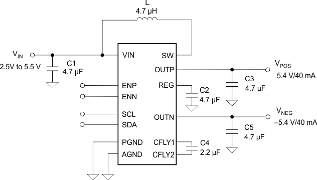
The TPS65132 family is designed to supply positive/negative driven applications. The device uses a single inductor scheme for both outputs to provide the user smallest solution size, a small bill-of-material as well as high efficiency. The devices offer best line and load regulation at low noise. With its input voltage range of 2.5 V to 5.5 V, it is optimized for products powered by single-cell batteries (Li-Ion, Ni-Li, Li-Polymer) and fixed 3.3-V and 5-V rails. The TPS656132 family provides 80 mA and 150 mA output current options with programmability to 40 mA. There are both CSP and QFN package options available.
PART NUMBER | PACKAGE | BODY SIZE (NOM.) |
---|---|---|
TPS65132 -B, -L, -T, -S |
DSBGA (15) | 2.11 mm × 1.51 mm |
TPS65132W | WQFN (20) | 4.00 mm × 3.00 mm |
space
space
Changes from G Revision (August 2015) to H Revision
Changes from F Revision (June 2015) to G Revision
Changes from E Revision (November 2014) to F Revision
Changes from D Revision (October 2014) to E Revision
Changes from C Revision (July 2014) to D Revision
Changes from B Revision (May 2014) to C Revision
Changes from A Revision (August 2013) to B Revision
Changes from * Revision (June 2013) to A Revision
PART NUMBER(1) | PRE-PROGRAMMED OUTPUT VOLTAGES |
IOUT_MAX | PRE-PROGRAMMED IOUT |
PRE-PROGRAMMED ACTIVE DISCHARGE(2) |
STARTUP TIME VPOS / VNEG (4) |
ISD | PACKAGE |
---|---|---|---|---|---|---|---|
TPS65132A | VPOS = 5.4 V VNEG = –5.4 V |
80 mA | 40 mA | VPOS / VNEG | FAST | 30 µA | CSP |
TPS65132A0 | VPOS = 5.0 V VNEG = –5.0 V |
||||||
TPS65132B | VPOS = 5.4 V VNEG = –5.4V |
80 mA | 40 mA | VPOS / VNEG | FAST | 130 nA | CSP |
TPS65132B0 | VPOS = 5.0 V VNEG = –5.0 V |
||||||
TPS65132B5 | VPOS = 5.5 V VNEG = –5.5 V |
||||||
TPS65132B2 | VPOS = 5.2 V VNEG = –5.2 V |
80 mA | 40 mA | VPOS / VNEG | SLOW | 130 nA | CSP |
TPS65132L | VPOS = 5.4 V VNEG = –5.4 V |
||||||
TPS65132L0 | VPOS = 5.0 V VNEG = –5.0 V |
||||||
TPS65132L1 (3) | VPOS = 5.1 V VNEG = –5.1 V |
80 mA | 40 mA | VPOS / VNEG | SLOW | 130 nA | CSP |
TPS65132T6 | VPOS = 5.6 V VNEG = –5.6 V |
80 mA | 80 mA | VPOS / VNEG | SLOW | 130 nA | CSP |
TPS65132S | VPOS = 5.4 V VNEG = –5.4 V |
150 mA | 80 mA | VPOS / VNEG | SLOW | 130 nA | CSP |
TPS65132W | VPOS = 5.4 V VNEG = –5.4 V |
80 mA | 80 mA | VPOS / VNEG | SLOW | 130 nA | QFN |
PIN | I/O | DESCRIPTION | ||
---|---|---|---|---|
NAME | Ax, Bx, Lx, Tx | Sx | ||
AGND | D2 | D2 | — | Analog ground |
CFLY1 | C3 | C3 | I/O | Negative charge pump flying capacitor pin |
CFLY2 | A3 | A3 | I/O | Negative charge pump flying capacitor pin |
EN | — | B1 | Enable pin (sequence programmed) | |
ENN | A1 | — | I | Enable pin for VNEG rail |
ENP | B1 | B1 | I | Enable pin for VPOS rail |
OUTP | E3 | E3 | O | Output pin of the LDO (VPOS) |
OUTN | A2 | A2 | O | Output pin of the negative charge pump (VNEG) |
PGND | B3 | B3 | — | Power ground |
E1 | E1 | |||
REG | D3 | D3 | I/O | Boost converter output pin |
E2 | E2 | |||
SCL | B2 | B2 | I/O | I²C interface clock signal pin |
SDA | C2 | C2 | I/O | I²C interface data signal pin |
SW | D1 | D1 | I/O | Switch pin of the boost converter |
SYNC | — | A1 | I | Synchronization pin. 150 mA current enabled if this pin is pulled HIGH. |
VIN | C1 | C1 | I | Input voltage supply pin |
PIN | I/O | DESCRIPTION | |
---|---|---|---|
NAME | Wx | ||
AGND | 3 | — | Analog ground |
17 | |||
CFLY1 | 13 | I/O | Negative charge pump flying capacitor pin |
CFLY2 | 10 | I/O | Negative charge pump flying capacitor pin |
ENN | 6 | I | Enable pin for VNEG rail |
ENP | 5 | I | Enable pin for VPOS rail |
OUTP | 16 | O | Output pin of the LDO (VPOS) |
15 | |||
OUTN | 9 | O | Output pin of the negative charge pump (VNEG) |
PGND | 1 | — | Power ground |
2 | |||
11 | |||
12 | |||
REG | 14 | I/O | Boost converter output pin |
18 | |||
SCL | 8 | I/O | I²C interface clock signal pin |
SDA | 7 | I/O | I²C interface data signal pin |
SW | 19 | I/O | Switch pin of the boost converter |
20 | |||
VIN | 4 | I | Input voltage supply pin |
VALUE | UNIT | |||
---|---|---|---|---|
MIN | MAX | |||
Voltage range | CFLY1, EN, ENN, ENP, OUTP, REG, SCL, SDA, SW, SYNC, VIN | –0.3 | 7 | V |
CFLY2, OUTN | –7 | 0.3 | V | |
Continuous total power dissipation | See Thermal Information | |||
Operating junction temperature, TJ | –40 | 150 | °C | |
Operating ambient temperature, TA | –40 | 85 | °C | |
Storage temperature, Tstg | –65 | 150 | °C |
VALUE | UNIT | |||
---|---|---|---|---|
VESD | Human body model (HBM), per ANSI/ESDA/JEDEC JS-001, all pins(1) | ±2000 | V | |
Charged device model (CDM) per JEDEC specification JESD22-C101, all pins(2) | ±500 | V |
MIN | TYP | MAX | UNIT | ||
---|---|---|---|---|---|
VIN | Input voltage range | 2.5 | 5.5 | V | |
L | Inductor(1) | 2.2 | 4.7 | µH | |
CIN | Input capacitor(1)(2) | 4.7 | µF | ||
CFLY | Flying capacitor(1)(2) | 2.2 | µF | ||
COUTP, COUTN, CREG | Output capacitors(1)(2) | 4.7 | µF | ||
TA | Operating ambient temperature | –40 | 85 | °C | |
TJ | Operating junction temperature | –40 | 125 | °C |
THERMAL METRIC(1) | TPS65132 | TPS65132 | UNIT | |
---|---|---|---|---|
YFF | RVC | |||
(15) BALLS | (20) PINS | |||
RθJA | Junction-to-ambient thermal resistance | 76.5 | 39.0 | °C/W |
RθJCtop | Junction-to-case (top) thermal resistance | 0.2 | 42.7 | °C/W |
RθJB | Junction-to-board thermal resistance | 44 | 13.6 | °C/W |
ψJT | Junction-to-top characterization parameter | 1.6 | 0.6 | °C/W |
ψJB | Junction-to-board characterization parameter | 43.4 | 13.6 | °C/W |
RθJCbot | Junction-to-case (bottom) thermal resistance | N/A | 3.8 | °C/W |
PARAMETER | TEST CONDITIONS | MIN | TYP | MAX | UNIT | |
---|---|---|---|---|---|---|
fSCL | SCL clock frequency | Standard mode | 100 | kHz | ||
Fast mode | 400 | kHz | ||||
tLOW | LOW period of the SCL clock | Standard mode | 4.7 | µs | ||
Fast mode | 1.3 | µs | ||||
tHIGH | HIGH period of the SCL clock | Standard mode | 4.0 | µs | ||
Fast mode | 600 | ns | ||||
tBUF | Bus free time between a STOP and START condition | Standard mode | 4.7 | µs | ||
Fast mode | 1.3 | µs | ||||
thd;STA | Hold time for a repeated START condition | Standard mode | 4.0 | µs | ||
Fast mode | 600 | ns | ||||
tsu;STA | Setup time for a repeated START condition | Standard mode | 4.7 | µs | ||
Fast mode | 600 | ns | ||||
tsu;DAT | Data setup time | Standard mode | 250 | ns | ||
Fast mode | 100 | ns | ||||
thd;DAT | Data hold time | Standard mode | 0.05 | 3.45 | µs | |
Fast mode | 0.05 | 0.9 | µs | |||
tRCL1 | Rise time of SCL signal after a repeated START condition and after an acknowledge bit | Standard mode | 20 + 0.1CB | 1000 | ns | |
Fast mode | 20 + 0.1CB | 1000 | ns | |||
tRCL | Rise time of SCL signal | Standard mode | 20 + 0.1CB | 1000 | ns | |
Fast mode | 20 + 0.1CB | 300 | ns | |||
tFCL | Fall time of SCL signal | Standard mode | 20 + 0.1CB | 300 | ns | |
Fast mode | 20 + 0.1CB | 300 | ns | |||
tRDA | Rise time of SDA signal | Standard mode | 20 + 0.1CB | 1000 | ns | |
Fast mode | 20 + 0.1CB | 300 | ns | |||
tFDA | Fall time of SDA signal | Standard mode | 20 + 0.1CB | 300 | ns | |
Fast mode | 20 + 0.1CB | 300 | ns | |||
tsu;STO | Setup time for STOP condition | Standard mode | 4.0 | µs | ||
Fast mode | 600 | ns | ||||
CB | Capacitive load for SDA and SCL | 0.4 | nF |