SLVSFM6A August 2020 – July 2021 TPS65994AD
PRODUCTION DATA
- 1 Features
- 2 Applications
- 3 Description
- 4 Revision History
- 5 Pin Configuration and Functions
-
6 Specifications
- 6.1 Absolute Maximum Ratings
- 6.2 ESD Ratings
- 6.3 Recommended Operating Conditions
- 6.4 Recommended Capacitance
- 6.5 Thermal Information
- 6.6 Power Supply Characteristics
- 6.7 Power Consumption
- 6.8 PP_5V Power Switch Characteristics
- 6.9 PP_EXT Power Switch Characteristics
- 6.10 Power Path Supervisory
- 6.11 CC Cable Detection Parameters
- 6.12 CC VCONN Parameters
- 6.13 CC PHY Parameters
- 6.14 Thermal Shutdown Characteristics
- 6.15 ADC Characteristics
- 6.16 Input/Output (I/O) Characteristics
- 6.17 I2C Requirements and Characteristics
- 6.18 Typical Characteristics
- 7 Parameter Measurement Information
-
8 Detailed Description
- 8.1 Overview
- 8.2 Functional Block Diagram
- 8.3
Feature Description
- 8.3.1 USB-PD Physical Layer
- 8.3.2 Power Management
- 8.3.3
Power Paths
- 8.3.3.1
Internal Sourcing Power Paths
- 8.3.3.1.1 PP_5Vx Current Clamping
- 8.3.3.1.2 PP_5Vx Local Overtemperature Shut Down (OTSD)
- 8.3.3.1.3 PP_5Vx Current Sense
- 8.3.3.1.4 PP_5Vx OVP
- 8.3.3.1.5 PP_5Vx UVLO
- 8.3.3.1.6 PP_5Vx Reverse Current Protection
- 8.3.3.1.7 Fast Role Swap
- 8.3.3.1.8 PP_CABLE Current Clamp
- 8.3.3.1.9 PP_CABLE Local Overtemperature Shut Down (OTSD)
- 8.3.3.1.10 PP_CABLE UVLO
- 8.3.3.2 Sink Path Control
- 8.3.3.1
Internal Sourcing Power Paths
- 8.3.4 Cable Plug and Orientation Detection
- 8.3.5 Default Behavior Configuration (ADCIN1, ADCIN2)
- 8.3.6 ADC
- 8.3.7 DisplayPort Hot-Plug Detect (HPD)
- 8.3.8 Digital Interfaces
- 8.3.9 Digital Core
- 8.3.10 I2C Interface
- 8.4 Device Functional Modes
- 9 Application and Implementation
- 10Power Supply Recommendations
- 11Layout
- 12Device and Documentation Support
- 13Mechanical, Packaging, and Orderable Information
Package Options
Refer to the PDF data sheet for device specific package drawings
Mechanical Data (Package|Pins)
- RSL|48
Thermal pad, mechanical data (Package|Pins)
Orderable Information
8.3.3.2.2 Reverse-Current Protection (RCP)
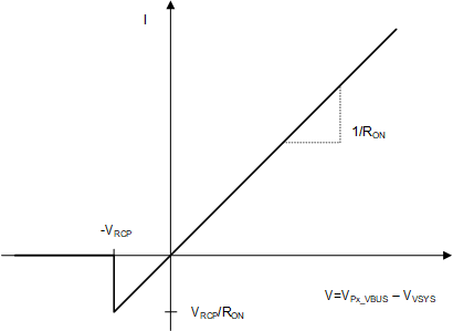
The VSYS gate control circuit monitors the VSYS and Px_VBUS voltages and detects reverse current when the VVSYS surpasses VPx_VBUS by more than VRCP. When the reverse current condition is detected, Px_GATE_VBUS is disabled within tPx_GATE_VBUS_RCP. When the reverse current condition is cleared, Px_GATE_VBUS is re-enabled within tPx_GATE_VBUS_ON. This limits the amount of reverse current that may flow from VSYS to Px_VBUS through the external N-ch MOSFETs.
In reverse current protection mode, the power switch controlled by Px_GATE_VBUS is allowed to behave resistively until the current reaches VRCP/ RON and then blocks reverse current from VSYS to Px_VBUS, where RON is the resistance of the external back-to-back N-ch MOSFET. Figure 8-14 shows the behavior of the switch.
 Figure 8-14 Switch I-V Curve for RCP on External Switches