JAJSSY9 February   2024 ADC12DL1500 , ADC12DL2500 , ADC12DL500

PRODUCTION DATA  

  1.   1
  2. 特長
  3. アプリケーション
  4. 概要
  5. Pin Configuration and Functions
  6. Specifications
    1. 5.1  Absolute Maximum Ratings
    2. 5.2  ESD Ratings
    3. 5.3  Recommended Operating Conditions
    4. 5.4  Thermal Information
    5. 5.5  Electrical Characteristics: DC Specifications
    6. 5.6  Electrical Characteristics: Power Consumption
    7. 5.7  Electrical Characteristics: AC Specifications (Dual-Channel Mode)
    8. 5.8  Electrical Characteristics: AC Specifications (Single-Channel Mode)
    9. 5.9  Timing Requirements
    10. 5.10 Switching Characteristics
    11. 5.11 Timing Diagrams
    12. 5.12 Typical Characteristics - ADC12DL500
    13. 5.13 Typical Characteristics - ADC12DL1500 (1GSPS)
    14. 5.14 Typical Characteristics - ADC12DL1500 (1.5GSPS)
    15. 5.15 Typical Characteristics - ADC12DL2500 (2GSPS)
    16. 5.16 Typical Characteristics - ADC12DL2500 (2.5GSPS)
  7. Detailed Description
    1. 6.1 Overview
    2. 6.2 Functional Block Diagram
    3. 6.3 Feature Description
      1. 6.3.1 Analog Inputs
        1. 6.3.1.1 Analog Input Protection
        2. 6.3.1.2 Full-Scale Voltage (VFS) Adjustment
        3. 6.3.1.3 Analog Input Offset Adjust
      2. 6.3.2 ADC Core
        1. 6.3.2.1 ADC Theory of Operation
        2. 6.3.2.2 ADC Core Calibration
        3. 6.3.2.3 ADC Overrange Detection
        4. 6.3.2.4 Code Error Rate (CER)
        5. 6.3.2.5 Internal Dither
      3. 6.3.3 Timestamp
      4. 6.3.4 Clocking
        1. 6.3.4.1 Noiseless Aperture Delay Adjustment (tAD Adjust)
        2. 6.3.4.2 Aperture Delay Ramp Control (TAD_RAMP)
        3. 6.3.4.3 SYSREF Capture for Multi-Device Synchronization and Deterministic Latency
          1. 6.3.4.3.1 SYSREF Position Detector and Sampling Position Selection (SYSREF Windowing)
          2. 6.3.4.3.2 Automatic SYSREF Calibration
      5. 6.3.5 LVDS Digital Interface
        1. 6.3.5.1 Multi-Device Synchronization and Deterministic Latency Using Strobes
          1. 6.3.5.1.1 Dedicated Strobe Pins
          2. 6.3.5.1.2 Reduced Width Interface With Dedicated Strobe Pins
          3. 6.3.5.1.3 LSB Replacement With a Strobe
          4. 6.3.5.1.4 Strobe Over All Data Pairs
      6. 6.3.6 Alarm Monitoring
        1. 6.3.6.1 Clock Upset Detection
      7. 6.3.7 Temperature Monitoring Diode
      8. 6.3.8 Analog Reference Voltage
    4. 6.4 Device Functional Modes
      1. 6.4.1 Dual-Channel Mode (Non-DES Mode)
      2. 6.4.2 Internal Dither Modes
      3. 6.4.3 Single-Channel Mode (DES Mode)
      4. 6.4.4 LVDS Output Driver Modes
      5. 6.4.5 LVDS Output Modes
        1. 6.4.5.1 Staggered Output Mode
        2. 6.4.5.2 Aligned Output Mode
        3. 6.4.5.3 Reducing the Number of Strobes
        4. 6.4.5.4 Reducing the Number of Data Clocks
        5. 6.4.5.5 Scrambling
        6. 6.4.5.6 Digital Interface Test Patterns and LVSD SYNC Functionality
          1. 6.4.5.6.1 Active Pattern
          2. 6.4.5.6.2 Synchronization Pattern
          3. 6.4.5.6.3 User-Defined Test Pattern
      6. 6.4.6 Power-Down Modes
      7. 6.4.7 Calibration Modes and Trimming
        1. 6.4.7.1 Foreground Calibration Mode
      8. 6.4.8 Offset Calibration
      9. 6.4.9 Trimming
    5. 6.5 Programming
      1. 6.5.1 Using the Serial Interface
        1. 6.5.1.1 SCS
        2. 6.5.1.2 SCLK
        3. 6.5.1.3 SDI
        4. 6.5.1.4 SDO
        5. 6.5.1.5 80
        6. 6.5.1.6 Streaming Mode
        7. 6.5.1.7 82
  8. Application and Implementation
    1. 7.1 Application Information
    2. 7.2 Typical Applications
      1. 7.2.1 Reconfigurable Dual-Channel 2.5GSPS or Single-Channel 5GSPS Oscilloscope
        1. 7.2.1.1 Design Requirements
          1. 7.2.1.1.1 Input Signal Path
          2. 7.2.1.1.2 Clocking
          3. 7.2.1.1.3 ADC12DLx500
        2. 7.2.1.2 Application Curves
    3. 7.3 Initialization Set Up
    4. 7.4 Power Supply Recommendations
      1. 7.4.1 Power Sequencing
    5. 7.5 Layout
      1. 7.5.1 Layout Guidelines
      2. 7.5.2 Layout Example
  9. Register Maps
    1. 8.1 SPI_REGISTER_MAP Registers
  10. Device and Documentation Support
    1. 9.1 Device Support
      1. 9.1.1 Development Support
    2. 9.2 ドキュメントの更新通知を受け取る方法
    3. 9.3 サポート・リソース
    4. 9.4 Trademarks
    5. 9.5 静電気放電に関する注意事項
    6. 9.6 用語集
  11. 10Revision History
  12. 11Mechanical, Packaging, and Orderable Information

パッケージ・オプション

メカニカル・データ(パッケージ|ピン)
サーマルパッド・メカニカル・データ
発注情報

概要

ADC12DL500、ADC12DL1500、ADC12DL2500 は A/D コンバータ (ADC) のファミリで、デュアル チャネル モードで最大 500MSPS、1.5GSPS、2.5GSPS、シングル チャネル モードで最大 1GSPS、3GSPS、5GSPS をサンプリングできます。チャネル数 (デュアル チャネル モード) とサンプル レート (シングル チャネル モード) のトレードオフをプログラム可能なため、多くのチャネル数や広い瞬間的な信号帯域幅アプリケーションの両方の要求に対応する、柔軟なハードウェアを開発できます。

これらのデバイスはレイテンシが短い低電圧差動信号 (LVDS) インターフェイスを使用しており、レイテンシが重要なアプリケーションや、LVDS の単純性が好ましい場合に適しています。インターフェイスは最大48のデータ ペア、4つのダブル データ レート(DDR)クロック、および4つのストローブ信号を使用して、4つの12ビット データ バスに編成されます。このインターフェイスは、最高 1.6Gbps の信号速度をサポートします。ストローブ信号により、バス間や複数のデバイス間の同期が簡単になります。このストローブは内部的に生成され、SYSREF 入力により決定論的なタイミングでリセット可能です。ノイズなしのアパーチャ遅延 (TAD) 調整や SYSREF のウィンドウ処理などの革新的な同期機能により、複数デバイスの同期がさらに簡単に行えます。
パッケージ情報
部品番号パッケージ (1)パッケージ サイズ(2)
ADC12DL500
ADC12DL1500
ADC12DL2500
FCBGA (256)17mm × 17mm
詳細については、セクション 11 を参照してください。
パッケージ サイズ (長さ × 幅) は公称値であり、該当する場合はピンも含まれます。
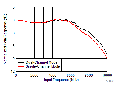
GUID-81B6B10B-F7C1-458A-BAF7-B3B30D708F7E-low.gifADC12DLx500 の周波数応答