JAJSF36L November 2008 – February 2019 ADC14155QML-SP
PRODUCTION DATA.
- 1 特長
- 2 アプリケーション
- 3 概要
- 4 改訂履歴
- 5 Pin Configuration and Functions
-
6 Specifications
- 6.1 Absolute Maximum Ratings
- 6.2 ESD Ratings
- 6.3 Recommended Operating Conditions
- 6.4 Thermal Information
- 6.5 ADC14155 Converter Electrical Characteristics DC Parameters
- 6.6 ADC14155 Converter Electrical Characteristics (Continued) DYNAMIC Parameters
- 6.7 ADC14155 Converter Electrical Characteristics (Continued) Logic and Power Supply Electrical Characteristics
- 6.8 ADC14155 Converter Electrical Characteristics (Continued) Timing and AC Characteristics
- 6.9 Timing Diagram
- 6.10 Transfer Characteristic
- 6.11 Typical Performance Characteristics, DNL, INL
- 6.12 Typical Performance Characteristics, Dynamic Performance
- 7 Detailed Description
- 8 Application and Implementation
- 9 Power Supply Recommendations
- 10Layout
- 11デバイスおよびドキュメントのサポート
- 12メカニカル、パッケージ、および注文情報
パッケージ・オプション
デバイスごとのパッケージ図は、PDF版データシートをご参照ください。
メカニカル・データ(パッケージ|ピン)
- NBA|48
サーマルパッド・メカニカル・データ
発注情報
7.3.3.1 Clock Inputs
The CLK+ and CLK– signals control the timing of the sampling process. The CLK_SEL/DF pin (pin 8) allows the user to configure the ADC for either differential or single-ended clock mode (see Clock Mode Select/Data Format (CLK_SEL/DF)). In differential clock mode, the two clock signals should be exactly 180° out of phase from each other and of the same amplitude. In the single-ended clock mode, the clock signal should be routed to the CLK+ input and the CLK– input should be tied to AGND in combination with the correct setting from Table 4.
To achieve the optimum noise performance, the clock inputs should be driven with a stable, low jitter clock signal. The clock input signal should also have a short transition region. This can be achieved by passing a low-jitter sinusoidal clock source through a high speed buffer gate. This configuration is shown in Figure 24. The trace carrying the clock signal should be as short as possible and should not cross any other signal line, analog or digital, not even at 90°. Figure 24 shows the recommended clock input circuit.
The clock signal also drives an internal state machine. If the clock is interrupted, or its frequency is too low, the charge on the internal capacitors can dissipate to the point where the accuracy of the output data will degrade. This will limit the minimum sample rate.
The clock line should be terminated at its source in the characteristic impedance of that line. Care should be taken to maintain a constant clock line impedance throughout the length of the line. Refer to Application Note AN-905 (SNLA035) for information on setting characteristic impedance.
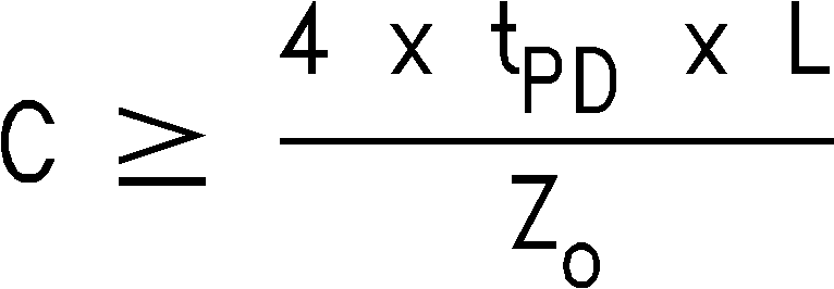
It is highly desirable that the source driving the ADC clock pins only drive that pin. However, if that source is used to drive other devices, then each driven pin should be AC terminated with a series RC to ground, such that the resistor value is equal to the characteristic impedance of the clock line and the capacitor value is

where tPD is the signal propagation rate down the clock line, "L" is the line length and ZO is the characteristic impedance of the clock line. This termination should be as close as possible to the ADC clock pin but beyond it as seen from the clock source. Typical tPD is about 150 ps/in (60 ps/cm) on FR-4 board material. The units of "L" and tPD should be the same (inches or centimeters).
The duty cycle of the clock signal can affect the performance of the A/D Converter. Because achieving a precise duty cycle is difficult, the ADC14155 has a Duty Cycle Stabilizer. It is designed to maintain performance over a clock duty cycle range of 30% to 70%.