JAJSF13C March 2018 – January 2019 ADS1260 , ADS1261
PRODUCTION DATA.
- 1 特長
- 2 アプリケーション
- 3 概要
- 4 改訂履歴
- 5 概要(続き)
- 6 Device Comparison Table
- 7 Pin Configuration and Functions
- 8 Specifications
- 9 Parameter Measurement Information
-
10Detailed Description
- 10.1 Overview
- 10.2 Functional Block Diagram
- 10.3 Feature Description
- 10.4
Device Functional Modes
- 10.4.1 Conversion Control
- 10.4.2 Chop Mode
- 10.4.3 AC-Excitation Mode
- 10.4.4 ADC Clock Mode
- 10.4.5 Power-Down Mode
- 10.4.6 Reset
- 10.4.7 Calibration
- 10.5 Programming
- 10.6
Register Map
- 10.6.1 Device Identification (ID) Register (address = 00h) [reset = xxh]
- 10.6.2 Device Status (STATUS) Register (address = 01h) [reset = 01h]
- 10.6.3 Mode 0 (MODE0) Register (address = 02h) [reset = 24h]
- 10.6.4 Mode 1 (MODE1) Register (address = 03h) [reset = 01h]
- 10.6.5 Mode 2 (MODE2) Register (address = 04h) [reset = 00h]
- 10.6.6 Mode 3 (MODE3) Register (address = 05h) [reset = 00h]
- 10.6.7 Reference Configuration (REF) Register (address = 06h) [reset = 05h]
- 10.6.8 Offset Calibration (OFCALx) Registers (address = 07h, 08h, 09h) [reset = 00h, 00h, 00h]
- 10.6.9 Full-Scale Calibration (FSCALx) Registers (address = 0Ah, 0Bh, 0Ch) [reset = 00h, 00h, 40h]
- 10.6.10 IDAC Multiplexer (IMUX) Register (address = 0Dh) [reset = FFh]
- 10.6.11 IDAC Magnitude (IMAG) Register (address = 0Eh) [reset = 00h]
- 10.6.12 Reserved (RESERVED) Register (address = 0Fh) [reset = 00h]
- 10.6.13 PGA Configuration (PGA) Register (address = 10h) [reset = 00h]
- 10.6.14 Input Multiplexer (INPMUX) Register (address = 11h) [reset = FFh]
- 10.6.15 Input Bias (INPBIAS) Register (address = 12h) [reset = 00h]
- 11Application and Implementation
- 12Power Supply Recommendations
- 13Layout
- 14デバイスおよびドキュメントのサポート
- 15メカニカル、パッケージ、および注文情報
パッケージ・オプション
デバイスごとのパッケージ図は、PDF版データシートをご参照ください。
メカニカル・データ(パッケージ|ピン)
- RHB|32
サーマルパッド・メカニカル・データ
発注情報
11.2 Typical Application
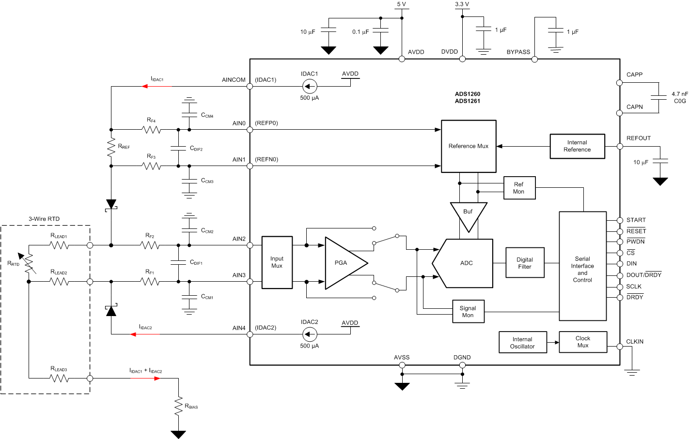
Figure 99 shows a fault-protected, 3-wire RTD application with hardware-based, lead-wire compensation. Two current sources are used together to compensate the RTD lead wire resistance. One current source (IDAC1) provides excitation to the RTD element through RLEAD1. The reference voltage of the ADC is derived directly from this current by resistor RREF. The second current source cancels lead-wire resistance by generating a voltage drop on lead-wire resistance RLEAD2 equal to the voltage drop of RLEAD1. Because the RRTD signal voltage is measured differentially via inputs AIN2 and AIN3, the voltages across the lead wire resistance cancel. Resistor RBIAS level-shifts the RTD signal voltage to within the ADC input range. The current sources route to the RTD element through low VF diodes to provide input fault protection.
 Figure 99. RTD Element With 3-Wire Lead Resistance Compensation