JAJSOX0B March 2024 – November 2024 ADS127L18
PRODMIX
- 1
- 1 特長
- 2 アプリケーション
- 3 概要
- 4 Pin Configuration and Functions
- 5 Specifications
-
6 Parameter Measurement Information
- 6.1 Offset Error Measurement
- 6.2 Offset Drift Measurement
- 6.3 Gain Error Measurement
- 6.4 Gain Drift Measurement
- 6.5 NMRR Measurement
- 6.6 CMRR Measurement
- 6.7 PSRR Measurement
- 6.8 SNR Measurement
- 6.9 INL Error Measurement
- 6.10 THD Measurement
- 6.11 IMD Measurement
- 6.12 SFDR Measurement
- 6.13 Noise Performance
-
7 Detailed Description
- 7.1 Overview
- 7.2 Functional Block Diagram
- 7.3 Feature Description
- 7.4 Device Functional Modes
- 7.5 Programming
- 8 Register Map
- 9 Application and Implementation
- 10Device and Documentation Support
- 11Revision History
- 12Mechanical, Packaging, and Orderable Information
7.3.8.2.4 Sinc3 + Sinc1 Filter
The sinc3 + sinc1 filter mode is the cascade of the sinc3 and a sinc1 filter. The OSR of the sinc3 stage is fixed (OSR = 32000) and the OSR of the sinc1 stage is programmable to 3 and 5. Table 7-7 summarizes the characteristics of the sinc3 + sinc1 filter.
| MODE | fCLK (MHz) |
OSR (A × B) (1) |
DATA RATE (SPS) | –3dB
FREQUENCY (Hz) |
LATENCY
(ms) |
NMRR AT FIRST NULL (dB) | |
|---|---|---|---|---|---|---|---|
| 2% CLOCK TOLERANCE | 6% CLOCK TOLERANCE | ||||||
| Max speed | 32.768 | 96000 (32000 × 3) |
170 | 69 | 9.77 | 34 | 26 |
| High speed | 25.6 | 133.3 | 54 | 12.5 | |||
| Mid speed | 12.8 | 66.6 | 27 | 25 | |||
| Low speed | 3.2 | 16.7 | 6.7 | 100 | |||
| Max speed | 32.768 | 160000 (32000 × 5) |
102 | 43.5 | 13.7 | 34 | 26 |
| High speed | 25.6 | 80 | 34 | 17.5 | |||
| Mid speed | 12.8 | 40 | 17 | 35 | |||
| Low speed | 3.2 | 10 | 4.2 | 140 | |||
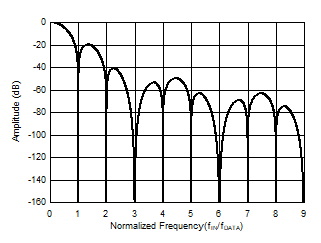
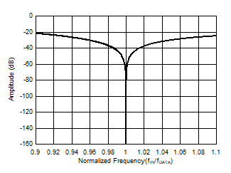
Figure 7-23 shows the frequency response of the sinc3 + sinc1 filter. The frequency response exhibits the characteristic sinc filter response lobes and nulls. The nulls occur at fDATA and at multiples thereof. Figure 7-24 shows the detailed response in the region of 0.9 to 1.1 · fIN / fDATA.
 Figure 7-23 Sinc3 + Sinc1 Frequency
Response
 Figure 7-24 Detail Sinc3 + Sinc1
Frequency Response