JAJSHV4C January 2014 – August 2019 ADS1283
PRODUCTION DATA.
- 1 特長
- 2 アプリケーション
- 3 概要
- 4 改訂履歴
- 5 Pin Configuration and Functions
- 6 Specifications
- 7 Parameter Measurement Information
-
8 Detailed Description
- 8.1 Overview
- 8.2 Functional Block Diagram
- 8.3 Feature Description
- 8.4
Device Functional Modes
- 8.4.1 Synchronization (SYNC PIN and SYNC Command)
- 8.4.2 Reset (RESET Pin and Reset Command)
- 8.4.3 Power-Down (PWDN Pin and STANDBY Command)
- 8.4.4 Power-On Sequence
- 8.4.5 DVDD Power Supply
- 8.4.6 Serial Interface
- 8.4.7 Data Format
- 8.4.8 Reading Data
- 8.4.9 One-Shot Operation
- 8.4.10 Offset and Full-Scale Calibration Registers
- 8.4.11 Calibration Commands (OFSCAL and GANCAL)
- 8.4.12 User Calibration
- 8.5
Programming
- 8.5.1
Commands
- 8.5.1.1 SDATAC Requirements
- 8.5.1.2 WAKEUP: Wake-Up From Standby Mode
- 8.5.1.3 STANDBY: Standby Mode
- 8.5.1.4 SYNC: Synchronize the Analog-to-Digital Conversion
- 8.5.1.5 RESET: Reset the Device
- 8.5.1.6 RDATAC: Read Data Continuous
- 8.5.1.7 SDATAC: Stop Read Data Continuous
- 8.5.1.8 RDATA: Read Data by Command
- 8.5.1.9 RREG: Read Register Data
- 8.5.1.10 WREG: Write to Register
- 8.5.1.11 OFSCAL: Offset Calibration
- 8.5.1.12 GANCAL: Gain Calibration
- 8.5.1
Commands
- 8.6
Register Maps
- 8.6.1
Register Descriptions
- 8.6.1.1 ID_CFG: ID_Configuration Register (address = 00h) [reset =x0h]
- 8.6.1.2 CONFIG0: Configuration Register 0 (address = 01h) [reset = 52h]
- 8.6.1.3 CONFIG1: Configuration Register 1 (address = 02h) [reset = 08h]
- 8.6.1.4 HPF0 and HPF1 Registers
- 8.6.1.5 OFC0, OFC1, OFC2 Registers
- 8.6.1.6 FSC0, FSC1, FSC2 Registers
- 8.6.1
Register Descriptions
- 9 Application and Implementation
- 10デバイスおよびドキュメントのサポート
- 11メカニカル、パッケージ、および注文情報
8.4.1.1 Pulse-Sync Mode
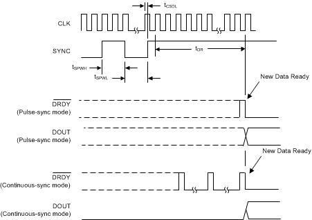
In pulse-sync mode, when a synchronization occurs (by pin or command), the ADS1283 unconditionally stops and restarts the conversion process. When the ADC synchronizes, the device resets the internal filter memory, DRDY goes high, and after the digital filter has settled, new conversion data are available as shown in Figure 45 and Table 12.
Table 12. Pulse-Sync Timing for Figure 45 and Figure 46
| PARAMETER | MIN | MAX | UNIT | |
|---|---|---|---|---|
| tCSDL | CLK rising edge to SYNC rising edge(2) | 30 | –30 | ns |
| tSYNC | SYNC clock period(1) | 1 | Infinite | n / fDATA |
| tSPWH, L | SYNC pulse width, high or low | 2 | 1 / fCLK | |
| tDR | Time for data ready (SINC filter) | See Table 13 | ||
| Time for data ready (FIR filter) | 62.98046875 / fDATA + 468 / fCLK | |||
Table 13. tDR Time for Data Ready (Sinc Filter)
| fDATA (kSPS) | fCLK CYCLES(1) |
|---|---|
| 128 | 440 |
| 64 | 616 |
| 32 | 968 |
| 16 | 1672 |
| 8 | 2824 |
Table 13 is referenced by Table 12 and Table 15.
Observe the timing restriction of SYNC rising edge to CLK rising edge as shown in Figure 45 and Table 12. Synchronization occurs on the next rising CLK edge after the rising edge of the SYNC, or after the eighth rising SCLK edge when synchronized by command. To synchronize multiple ADCs, broadcast the command to the ADCs simultaneously.
