JAJSVV8 December   2024 AFE5401-EP

PRODUCTION DATA  

  1.   1
  2. 特長
  3. アプリケーション
  4. 概要
  5. Pin Configuration and Functions
    1.     Pin Functions
  6. Specifications
    1. 5.1  Absolute Maximum Ratings
    2. 5.2  ESD Ratings
    3. 5.3  Recommended Operating Conditions
    4. 5.4  Thermal Information
    5. 5.5  Electrical Characteristics
    6. 5.6  Digital Characteristics
    7. 5.7  Timing Requirements: Output Interface
    8. 5.8  Timing Requirements: RESET
    9. 5.9  Timing Requirements: Serial Interface Operation
    10. 5.10 Typical Characteristics
  7. Parameter Measurement Information
    1. 6.1 Timing Requirements: Across Output Serialization Modes
  8. Detailed Description
    1. 7.1 Overview
    2. 7.2 Functional Block Diagram
    3. 7.3 Feature Description
      1. 7.3.1 Low-Noise Amplifier (LNA)
      2. 7.3.2 Programmable Gain Amplifier (PGA)
      3. 7.3.3 Antialiasing Filter
      4. 7.3.4 Analog-to-Digital Converter (ADC)
      5. 7.3.5 Digital Gain
      6. 7.3.6 Input Clock Divider
      7. 7.3.7 Data Output Serialization
      8. 7.3.8 Setting the Input Common-Mode Voltage for the Analog Inputs
        1. 7.3.8.1 Main Channels
        2. 7.3.8.2 Auxiliary Channel
    4. 7.4 Device Functional Modes
      1. 7.4.1 Equalizer Mode
      2. 7.4.2 Data Output Mode
        1. 7.4.2.1 Header
        2. 7.4.2.2 Test Pattern Mode
      3. 7.4.3 Parity
      4. 7.4.4 Standby, Power-Down Mode
      5. 7.4.5 Digital Filtering to Improve Stop-Band Attenuation
        1. 7.4.5.1 Decimate-by-2 Mode
        2. 7.4.5.2 Decimate-by-4 Mode
      6. 7.4.6 Diagnostic Mode
      7. 7.4.7 Signal Chain Probe
    5. 7.5 Programming
      1. 7.5.1 Serial Interface
      2. 7.5.2 Register Initialization
        1. 7.5.2.1 Register Write Mode
        2. 7.5.2.2 Register Read Mode
      3. 7.5.3 CMOS Output Interface
        1. 7.5.3.1 Synchronization and Triggering
    6. 7.6 Register Maps
      1. 7.6.1 Functional Register Map
      2. 7.6.2 Register Descriptions
  9. Application and Implementation
    1. 8.1 Application Information
    2. 8.2 Typical Application
      1. 8.2.1 Design Requirements
      2. 8.2.2 Detailed Design Procedure
      3. 8.2.3 Application Curves
    3. 8.3 Power Supply Recommendations
      1. 8.3.1 Power Supply Sequencing
      2. 8.3.2 Power Supply Decoupling
    4. 8.4 Layout
      1. 8.4.1 Layout Guidelines
      2. 8.4.2 Layout Example
  10. Revision History
  11. 10Device and Documentation Support
    1. 10.1 Documentation Support
      1. 10.1.1 Related Documentation
    2. 10.2 Receiving Notification of Documentation Updates
    3. 10.3 Community Resources
    4. 10.4 Trademarks
  12. 11Mechanical, Packaging, and Orderable Information

パッケージ・オプション

メカニカル・データ(パッケージ|ピン)
サーマルパッド・メカニカル・データ
発注情報

概要

AFE5401-EP は、統合レベルを重視するアプリケーションを対象としたアナログ フロント エンド (AFE) です。このデバイスには 4 つのチャネルがあり、各チャネルは低ノイズ アンプ (LNA)、プログラマブル イコライザ (EQ)、プログラマブル ゲイン アンプ (PGA)、アンチエイリアス フィルタで構成され、チャネルあたり 25MSPS の高速 12 ビット A/D コンバータ (ADC) に接続されています。

4 つの差動入力ペアはそれぞれ LNA によって増幅され、その後にプログラマブル ゲイン範囲が 0dB~30dB の PGA が接続されています。各チャネルについて、PGA と ADC の間にアンチエイリアス、ローパス フィルタ (LPF) も内蔵されています。

各 LNA、PGA、およびアンチエイリアス フィルタ出力は差動です (2VPP に制限)。アンチエイリアス フィルタは、オンチップの 12 ビット、25MSPS ADC を駆動します。4 つの ADC 出力は、12 ビットのパラレル CMOS 出力バスで多重化されます。

このデバイスは 9mm × 9mm の VQFN-64 パッケージで供給され、-40℃~+125℃の温度範囲で動作が規定されています。詳細については、AFE5401_info@list.ti.com にお問い合わせください。

製品情報(1)
部品番号パッケージパッケージ サイズ (公称) (2)
AFE5401-EPVQFN (64)9.00mm × 9.00mm
利用可能なすべてのパッケージについては、データシートの末尾にある注文情報を参照してください。
パッケージ サイズ (長さ×幅) は公称値であり、該当する場合はピンも含まれます
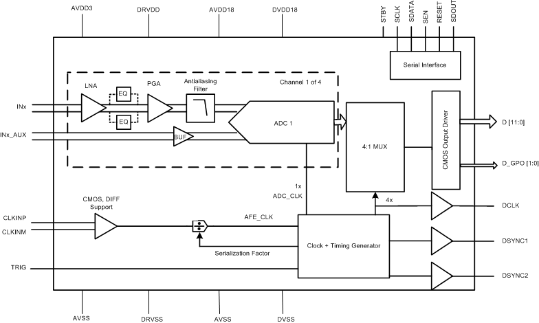
AFE5401-EP 概略回路図概略回路図