SLAS411D November 2004 – February 2016 DAC8811
PRODUCTION DATA.
- 1 Features
- 2 Applications
- 3 Description
- 4 Revision History
- 5 Device Comparison Table
- 6 Pin Configuration and Functions
- 7 Specifications
- 8 Detailed Description
- 9 Application and Implementation
- 10Power Supply Recommendations
- 11Layout
- 12Device and Documentation Support
- 13Mechanical, Packaging, and Orderable Information
パッケージ・オプション
メカニカル・データ(パッケージ|ピン)
サーマルパッド・メカニカル・データ
- DRB|8
発注情報
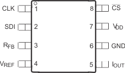
6 Pin Configuration and Functions
DRB Package
8-Pins VSON
Top View

DGK Package
8-Pins VSSOP
Top View

Pin Functions
| PIN | TYPE | DESCRIPTION | |
|---|---|---|---|
| NAME | NO. | ||
| CLK | 1 | I | Clock input; positive edge triggered clocks data into shift register |
| SDI | 2 | I | Serial register input; data loads directly into the shift register MSB first. Extra leading bits are ignored. |
| RFB | 3 | O | Internal matching feedback resistor. Connect to external op amp output. |
| VREF | 4 | I | DAC reference input pin. Establishes DAC full-scale voltage. Constant input resistance versus code. |
| IOUT | 5 | O | DAC current output. Connects to inverting terminal of external precision I/V op amp. |
| GND | 6 | G | Analog and digital ground. |
| VDD | 7 | I | Positive power supply input. Specified operating range of 2.7 V to 5.5 V. |
| CS | 8 | I | Chip-select; active low digital input. Transfers shift register data to DAC register on rising edge. See Table 1 for operation. |