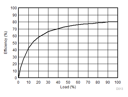
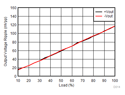
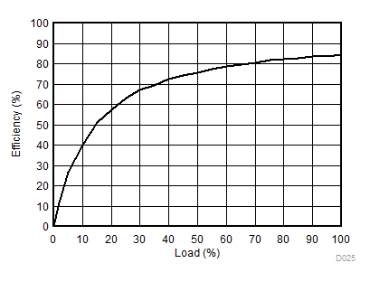
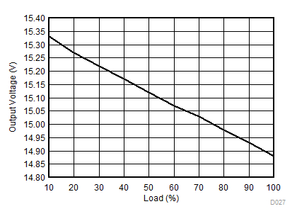
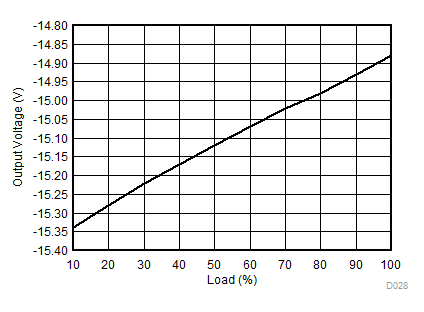
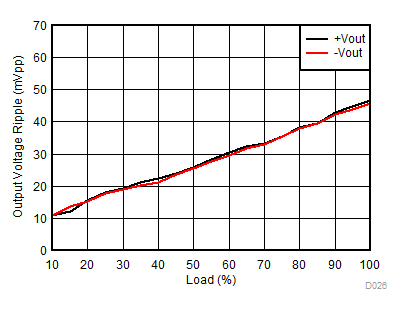
6.1 Absolute Maximum Ratings
over operating free-air temperature range (unless otherwise noted) (1)
|
MIN |
MAX |
UNIT |
| Input voltage |
+VS |
|
–0.5 |
6 |
V |
| 50ns transient |
–1.0 |
7 |
V |
| SYNCIN |
|
–0.5 |
+VS |
V |
| 50ns transient |
–1.0 |
6 |
V |
| Lead temperature (soldering, 10 s) |
|
260 |
°C |
| Storage temperature, Tstg |
–60 |
125 |
°C |
(1) Stresses beyond those listed under Absolute Maximum Ratings may cause permanent damage to the device. These are stress ratings only, which do not imply functional operation of the device at these or any other conditions beyond those indicated under Recommended Operating Conditions. Exposure to absolute-maximum-rated conditions for extended periods may affect device reliability.
6.2 ESD Ratings
|
VALUE |
UNIT |
| V(ESD) |
Electrostatic discharge |
Human-body model (HBM), per ANSI/ESDA/JEDEC JS-001 (1) |
±1000 |
V |
| Charged-device model (CDM), per JEDEC specification JESD22-C101 (2) |
±250 |
(1) JEDEC document JEP155 states that 500-V HBM allows safe manufacturing with a standard ESD control process.
(2) JEDEC document JEP157 states that 250-V CDM allows safe manufacturing with a standard ESD control process.
6.4 Electrical Characteristics
TA = 25°C, +VS = nominal, CIN = 2.2 µF, COUT = 1.0 µF, (unless otherwise noted)
| PARAMETER |
TEST CONDITIONS |
MIN |
TYP |
MAX |
UNIT |
| OUTPUT |
| POUT |
Output power |
Over +VS range, IOUT = 100% (full load) |
|
|
1 |
W |
| IOUT |
Output current |
|
DCPA10505 |
|
|
200 |
mA |
| DCPA10505D |
|
|
200(2) |
mA |
| DCPA10512 |
|
|
83 |
mA |
| DCPA10512D |
|
|
83(2) |
mA |
| DCPA10515 |
|
|
66 |
mA |
| DCPA10515D |
|
|
66(2) |
mA |
| VOUT |
Output voltage |
IOUT = 100% load (4) |
DCPA10505 |
|
5.0 |
|
V |
| DCPA10505D |
|
±5.0 |
|
V |
| DCPA10512 |
|
12.0 |
|
V |
| DCPA10512D |
|
±12.0 |
|
V |
| DCPA10515 |
|
15.0 |
|
V |
| DCPA10515D |
|
±15.0 |
|
V |
| Temperature variation |
–40°C ≤ TA ≤ 100°C, IOUT = 100% load |
|
0.02 |
|
%/°C |
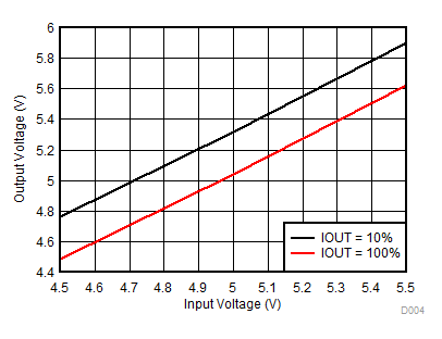
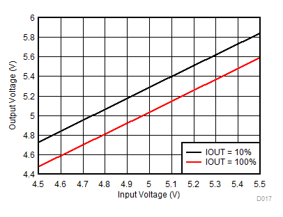
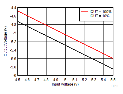
| Line regulation |
+VS(MIN) to +VS(TYP), IOUT = 10% load |
|
10% |
|
|
| +VS(TYP) to +VS(MAX), IOUT = 10% load |
|
10% |
|
|
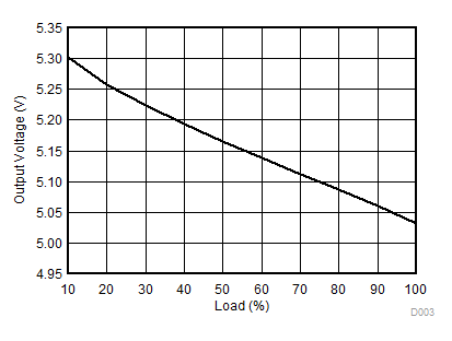
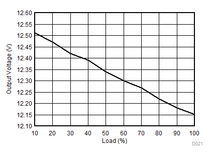
| Load regulation(1) |
10% to 100% load |
|
5% |
|
|
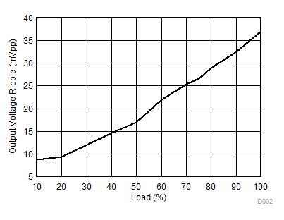
| VRIPPLE |
Output voltage ripple(5) |
COUT = 1 μF, IOUT = 50% |
|
20 |
|
mVPP |
| INPUT |
| +VS |
Input voltage range |
|
4.5 |
|
5.5 |
V |
| UVLO |
+VS Undervoltage lockout |
+VS increasing threshold |
|
|
2.25 |
V |
| +VS decreasing threshold |
1.7 |
|
|
V |
| IQ |
Quiescient current |
IOUT = 0% load |
DCPA10505 |
|
35 |
|
mA |
| DCPA10505D |
|
25 |
|
mA |
| DCPA10512 |
|
29 |
|
mA |
| DCPA10512D |
|
36 |
|
mA |
| DCPA10515 |
|
31 |
|
mA |
| DCPA10515D |
|
38 |
|
mA |
| ISOLATION |
| VISO |
Isolation |
1-second flash test, voltage |
DC |
2.0(6)(5) |
|
|
kVDC |
| AC |
1.5(6) |
|
|
kVrms |
| 1-second flash test, leakage current |
|
|
30 |
µA |
| Continuous working voltage across isolation barrier |
DC |
|
|
60 |
VDC |
| AC |
|
|
42.5 |
VAC |
| dV/dt |
|
|
50 |
V/ms |
| CISO |
Barrier capacitance |
VISO = 750 Vrms |
|
28 |
|
pF |
| PERFORMANCE |
|
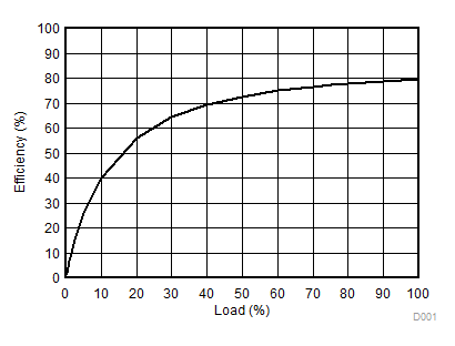
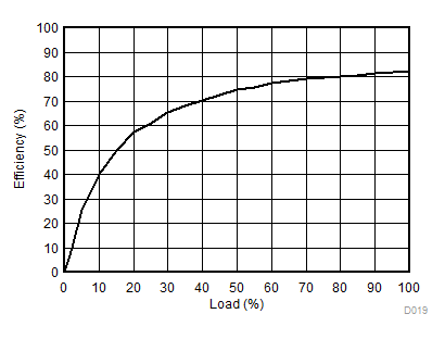
Efficiency |
IOUT = 100% |
DCPA10505 |
|
85% |
|
|
| DCPA10505D |
|
85% |
|
|
| DCPA10512 |
|
87% |
|
|
| DCPA10512D |
|
88% |
|
|
| DCPA10515 |
|
86% |
|
|
| DCPA10515D |
|
86% |
|
|
|
Transient response(5) |
50% to 100% load step |
DCPA10505 |
|
3.0% |
|
|
| DCPA10512 |
|
1.9% |
|
|
| DCPA10515 |
|
2.0% |
|
|
50% to 100% load step
per output(3) |
DCPA10505D |
|
2.7% |
|
|
| DCPA10512D |
|
2.0% |
|
|
| DCPA10515D |
|
1.6% |
|
|
| RELIABILITY |
|
Demonstrated |
TA = 55°C |
|
55 |
|
FITS |
| CAPACITANCE |
| CIN |
External input capacitance |
Ceramic |
2.2 |
|
|
µF |
| COUT |
External output capacitance |
Ceramic |
0.1 |
1.0 |
200 |
µF |
| THERMAL SHUTDOWN |
| TSD |
Die temperature at shutdown |
|
|
168 |
|
°C |
| ISD |
Shutdown current |
|
|
3 |
|
mA |
(1) Load regulation = (VOUT at 10% load – VOUT at 100%)/VOUT at 75% load
(2) IOUT1 + IOUT2
(3) Transient testing for dual output devices are tested with one output loaded with a 50% static load and the other output loaded with a 50% to 100% dynamic load step.
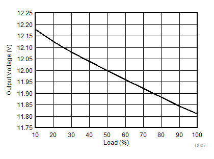
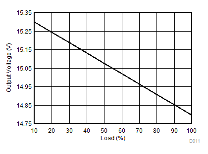
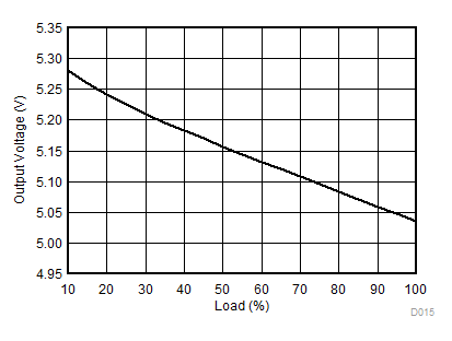
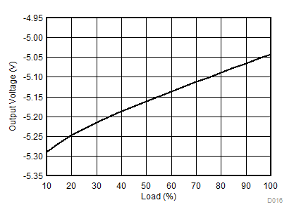
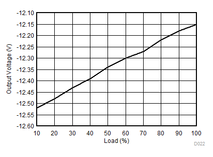
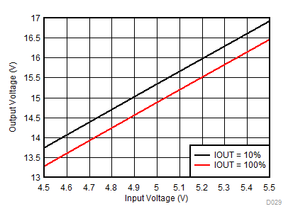
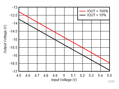
(4) See Load Regulation graphs in the Typical Characterization section for typical voltage at all load conditions.
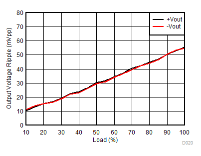
(5) Guaranteed by design. Not production tested.
