JAJSIM5A November   2020  – June 2022 DLP670S

PRODUCTION DATA  

  1. 特長
  2. アプリケーション
  3. 概要
  4. Revision History
  5. Pin Configuration and Functions
  6. Specifications
    1. 6.1  Absolute Maximum Ratings
    2. 6.2  Storage Conditions
    3. 6.3  ESD Ratings
    4. 6.4  Recommended Operating Conditions
    5. 6.5  Thermal Information
    6. 6.6  Electrical Characteristics
    7. 6.7  Capacitance at Recommended Operating Conditions
    8. 6.8  Timing Requirements
    9. 6.9  Typical Characteristics
    10. 6.10 System Mounting Interface Loads
    11. 6.11 Micromirror Array Physical Characteristics
    12. 6.12 Micromirror Array Optical Characteristics
    13. 6.13 Window Characteristics
    14. 6.14 Chipset Component Usage Specification
  7. Detailed Description
    1. 7.1 Overview
    2. 7.2 Functional Block Diagram
    3. 7.3 Feature Description
      1. 7.3.1 Power Interface
      2. 7.3.2 Timing
    4. 7.4 Device Functional Modes
    5. 7.5 Optical Interface and System Image Quality
      1. 7.5.1 Numerical Aperture and Stray Light Control
      2. 7.5.2 Pupil Match
      3. 7.5.3 Illumination Overfill
    6. 7.6 Micromirror Array Temperature Calculation
      1. 7.6.1 Micromirror Array Temperature Calculation using Illumination Power Density
      2. 7.6.2 Micromirror Array Temperature Calculation using Total Illumination Power
      3. 7.6.3 Micromirror Array Temperature Calculation using Screen Lumens
    7. 7.7 Micromirror Landed-On/Landed-Off Duty Cycle
      1. 7.7.1 Definition of Micromirror Landed-On/Landed-Off Duty Cycle
      2. 7.7.2 Landed Duty Cycle and Useful Life of the DMD
      3. 7.7.3 Landed Duty Cycle and Operational DMD Temperature
      4. 7.7.4 Estimating the Long-Term Average Landed Duty Cycle of a Product or Application
  8. Application and Implementation
    1. 8.1 Application Information
    2. 8.2 Typical Application
      1. 8.2.1 Design Requirements
      2. 8.2.2 Detailed Design Procedure
    3. 8.3 DMD Die Temperature Sensing
  9. Power Supply Recommendations
    1. 9.1 DMD Power Supply Power-Up Procedure
    2. 9.2 DMD Power Supply Power-Down Procedure
    3. 9.3 Restrictions on Hot Plugging and Hot Swapping
      1. 9.3.1 No Hot Plugging
      2. 9.3.2 No Hot Swapping
      3. 9.3.3 Intermittent or Voltage Power Spike Avoidance
  10. 10Layout
    1. 10.1 Layout Guidelines
      1. 10.1.1 Critical Signal Guidelines
      2. 10.1.2 Power Connection Guidelines
      3. 10.1.3 Noise Coupling Avoidance
    2. 10.2 Layout Example
      1. 10.2.1 Layers
      2. 10.2.2 Impedance Requirements
      3. 10.2.3 Trace Width, Spacing
        1. 10.2.3.1 Voltage Signals
  11. 11Device and Documentation Support
    1. 11.1 Third-Party Products Disclaimer
    2. 11.2 Device Support
      1. 11.2.1 Device Nomenclature
      2. 11.2.2 Device Markings
    3. 11.3 Documentation Support
      1. 11.3.1 Related Documentation
    4. 11.4 Receiving Notification of Documentation Updates
    5. 11.5 サポート・リソース
    6. 11.6 Trademarks
    7. 11.7 Electrostatic Discharge Caution
    8. 11.8 Glossary
  12. 12Mechanical, Packaging, and Orderable Information

パッケージ・オプション

メカニカル・データ(パッケージ|ピン)
サーマルパッド・メカニカル・データ
発注情報

概要

430 万個を超えるマイクロミラーを搭載した DLP670S デジタル・マイクロミラー・デバイス (DMD) は、入射光の振幅、方向、位相を変調する空間光変調器 (SLM) です。この DMD は、4 つの 2xLVDS 入力データ・バスとの組み合わせにより、非常に高速なパターン・レートで高分解能パターンを表示できます。DLP670S は高分解能で高速なパターン・レートを実現しており、産業用、医療用、および高度な画像処理アプリケーションを幅広くサポートするのに最適です。DLP670S の機能と動作の高い信頼性 は、デュアル DLPC900 デジタル・コントローラと組み合わせることで実現されます。この専用チップセットは、さまざまな最終製品ソリューションの要件を満たすのに必要な高いパターン・レートで、柔軟でプログラムしやすいパターンを提供します。

高分解能は、3Dマシン・ビジョン・アプリケーションで大型の物体をスキャンする際に直接的な利点があります。

DLP670S を使用して設計を開始する方法については、TI の DLP® 高度光制御テクノロジーのページをご覧ください。TI.com で利用できる DLP 高度光制御のリソースには、評価基板リファレンス・デザイン光学モジュール・メーカーDLP デザイン・ネットワーク・パートナーなどが含まれており、製品開発期間の短縮に役立ちます。

表 3-1 製品情報
部品番号 パッケージ 本体サイズ (公称)
DLP670S(1) FYR (350) 35mm × 32mm
利用可能なパッケージについては、このデータシートの末尾にある注文情報を参照してください。
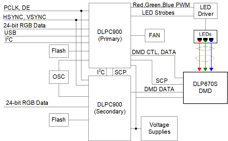
GUID-20210304-CA0I-2DJG-ZSSX-0FVPPH6PSV3C-low.pngDLP670S の概略回路図