JAJSFJ1 May 2018 DLPA4000
PRODUCTION DATA.
- 1 特長
- 2 アプリケーション
- 3 概要
- 4 改訂履歴
- 5 概要(続き)
- 6 Pin Configuration and Functions
- 7 Specifications
-
8 Detailed Description
- 8.1 Overview
- 8.2 Functional Block Description
- 8.3
Feature Description
- 8.3.1 Supply and Monitoring
- 8.3.2 Illumination
- 8.3.3 External Power MOSFET Selection
- 8.3.4 DMD Supplies
- 8.3.5 Buck Converters
- 8.3.6 Auxiliary LDOs
- 8.3.7 Measurement System
- 8.4 Device Functional Modes
- 8.5 Programming
- 8.6 Register Maps
- 9 Application and Implementation
- 10Power Supply Recommendations
- 11Layout
- 12デバイスおよびドキュメントのサポート
- 13メカニカル、パッケージ、および注文情報
8.3.1.1 Supply
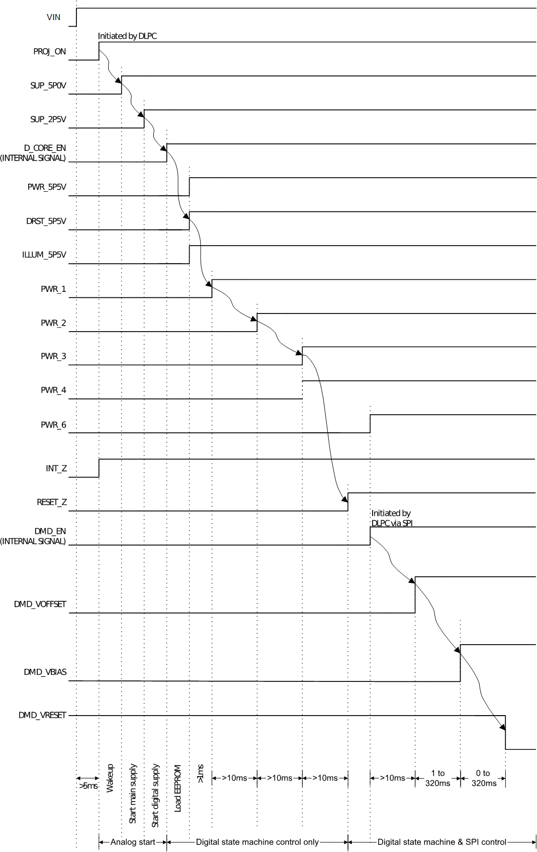
The specified input supply voltage for main supply (VIN) is between 16 V and 20 V. The typical specification is 19.5 V. When the device energizes, several internal power supplies become energized sequentially.(Figure 1). A sequential startup ensures that all the different blocks start in a certain order and prevent excessive startup currents. The main control to start the device is the control pin PROJ_ON. Once set high the basic analog circuitry is started that is needed to operate the digital and SPI interface. This circuitry is supplied by two LDO regulators that generate 2.5 V (SUP_2P5V) and 5 V (SUP_5P0V). These regulator voltages internal only. Do not load these regulator voltages externally. Make sure the output capacitance is 2.2 µF for the 2.5-V LDO (pin 91) and 4.7 µF for the 5-V LDO, (pin 92). After the LDO voltages reach the regulator levels, the digital core starts, and the Digital State Machine (DSM) controls the device.
Subsequently, the 5.5-V LDOs for various blocks start: PWR_5V5V, DRST_5P5V and ILLUM_5P5V. Then the DLPC buck converters (PWR_1 & PWR_2) start and followed by the DMD LDOs (PWR_3 & PWR_4).The device enables and is controllable by the DLPC (indicated by RESET_Z going high). At this point the general purpose buck converter (PWR_6) can start. Lastly the regulator that supplies the DMD starts. The DMD regulator generates the timing critical VOFFSET, VBIAS, and VRESET supplies.

NOTE:
Arrows indicate sequence of events automatically controlled by digital state machine. Other events are initiated under SPI control.