JAJSFJ1 May 2018 DLPA4000
PRODUCTION DATA.
- 1 特長
- 2 アプリケーション
- 3 概要
- 4 改訂履歴
- 5 概要(続き)
- 6 Pin Configuration and Functions
- 7 Specifications
-
8 Detailed Description
- 8.1 Overview
- 8.2 Functional Block Description
- 8.3
Feature Description
- 8.3.1 Supply and Monitoring
- 8.3.2 Illumination
- 8.3.3 External Power MOSFET Selection
- 8.3.4 DMD Supplies
- 8.3.5 Buck Converters
- 8.3.6 Auxiliary LDOs
- 8.3.7 Measurement System
- 8.4 Device Functional Modes
- 8.5 Programming
- 8.6 Register Maps
- 9 Application and Implementation
- 10Power Supply Recommendations
- 11Layout
- 12デバイスおよびドキュメントのサポート
- 13メカニカル、パッケージ、および注文情報
8.3.2.1 Programmable Gain Block
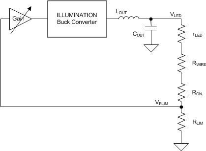
IDAC registers 0x03h to 0x08h determine the current through the LEDs, which is measured through the sense resistor RLIM. The device compares the voltage across RLIM with the current setting from the IDAC registers. The loop regulates the current to the set value.
 Figure 5. Programmable Gain Block in the Illumination Control Loop
 When current flows through an LED, a forward voltage builds up across the LED. The LED acts as a (low) differential resistance that is part of the load circuit for VLED. Together with the wire resistance (RWIRE) and the on-resistance (RON) of the MOSFET switch, the device creates a voltage divider with the RLIM resistor that is a factor in the loop gain of the ILED control. During normal conditions, the loop produces a well-regulated LED current up to 32 A.
Because this voltage divider is a component of the control loop, make sure to consider issues such as resistance and attenuation. For instance, when the application includes two LEDs connected in series, or when the application has relatively high wiring resistance, the loop gain reduces due to the extra attenuation caused by the increased series resistance of rLED + RWIRE +RON. As a result, the loop response time lowers. To compensate for this increased attenuation, increase the loop gain by selecting a higher gain for the programmable gain block. Use register 0x25h [3:0] to set the gain increase.
During normal operation the default gain setting (00h) suffices. In case of two LEDs connected in series a gain setting 01h or 02h suffices.
Wiring resistance also impacts the control-loop performance. Avoid unnecessary large wire length in the loop. Maintain a wiring resistance as low as possible to yield the highest efficiency. When wiring resistance continues to impact the response time of the loop, select an appropriate setting of the gain block. Also be aware of connector resistance and PCB tracks. Every milli-ohm of resistance counts.