JAJSD08E October 2015 – May 2024 DP83867CS , DP83867E , DP83867IS
PRODUCTION DATA
- 1
- 1 特長
- 2 アプリケーション
- 3 概要
- 4 Device Comparison
- 5 Pin Configuration and Functions
-
6 Specifications
- 6.1 Absolute Maximum Ratings
- 6.2 ESD Ratings
- 6.3 Recommended Operating Conditions
- 6.4 Thermal Information
- 6.5 Electrical Characteristics
- 6.6 Power-Up Timing
- 6.7 Reset Timing
- 6.8 MII Serial Management Timing
- 6.9 SGMII Timing
- 6.10 RGMII Timing
- 6.11 DP83867E Start of Frame Detection Timing
- 6.12 DP83867IS/CS Start of Frame Detection Timing
- 6.13 Timing Diagrams
- 6.14 Typical Characteristics
-
7 Detailed Description
- 7.1 Overview
- 7.2 Functional Block Diagram
- 7.3 Feature Description
- 7.4
Device Functional Modes
- 7.4.1 MAC Interfaces
- 7.4.2
Serial Management Interface
- 7.4.2.1
Extended Address Space Access
- 7.4.2.1.1 Write Address Operation
- 7.4.2.1.2 Read Address Operation
- 7.4.2.1.3 Write (No Post Increment) Operation
- 7.4.2.1.4 Read (No Post Increment) Operation
- 7.4.2.1.5 Write (Post Increment) Operation
- 7.4.2.1.6 Read (Post Increment) Operation
- 7.4.2.1.7 Example of Read Operation Using Indirect Register Access
- 7.4.2.1.8 Example of Write Operation Using Indirect Register Access
- 7.4.2.1
Extended Address Space Access
- 7.4.3
Auto-Negotiation
- 7.4.3.1 Speed and Duplex Selection - Priority Resolution
- 7.4.3.2 Master and Slave Resolution
- 7.4.3.3 Pause and Asymmetrical Pause Resolution
- 7.4.3.4 Next Page Support
- 7.4.3.5 Parallel Detection
- 7.4.3.6 Restart Auto-Negotiation
- 7.4.3.7 Enabling Auto-Negotiation Through Software
- 7.4.3.8 Auto-Negotiation Complete Time
- 7.4.3.9 Auto-MDIX Resolution
- 7.4.4 Loopback Mode
- 7.4.5 BIST Configuration
- 7.4.6 Cable Diagnostics
- 7.5 Programming
- 7.6
Register Maps
- 7.6.1 Basic Mode Control Register (BMCR)
- 7.6.2 Basic Mode Status Register (BMSR)
- 7.6.3 PHY Identifier Register #1 (PHYIDR1)
- 7.6.4 PHY Identifier Register #2 (PHYIDR2)
- 7.6.5 Auto-Negotiation Advertisement Register (ANAR)
- 7.6.6 Auto-Negotiation Link Partner Ability Register (ANLPAR) (BASE Page)
- 7.6.7 Auto-Negotiate Expansion Register (ANER)
- 7.6.8 Auto-Negotiation Next Page Transmit Register (ANNPTR)
- 7.6.9 Auto-Negotiation Next Page Receive Register (ANNPRR)
- 7.6.10 1000BASE-T Configuration Register (CFG1)
- 7.6.11 Status Register 1 (STS1)
- 7.6.12 Extended Register Addressing
- 7.6.13 1000BASE-T Status Register (1KSCR)
- 7.6.14 PHY Control Register (PHYCR)
- 7.6.15 PHY Status Register (PHYSTS)
- 7.6.16 MII Interrupt Control Register (MICR)
- 7.6.17 Interrupt Status Register (ISR)
- 7.6.18 Configuration Register 2 (CFG2)
- 7.6.19 Receiver Error Counter Register (RECR)
- 7.6.20 BIST Control Register (BISCR)
- 7.6.21 Status Register 2 (STS2)
- 7.6.22 LED Configuration Register 1 (LEDCR1)
- 7.6.23 LED Configuration Register 2 (LEDCR2)
- 7.6.24 LED Configuration Register (LEDCR3)
- 7.6.25 Configuration Register 3 (CFG3)
- 7.6.26 Control Register (CTRL)
- 7.6.27 Testmode Channel Control (TMCH_CTRL)
- 7.6.28 Robust Auto MDIX Timer Configuration Register (AMDIX_TMR_CFG)
- 7.6.29 Fast Link Drop Configuration Register (FLD_CFG)
- 7.6.30 Fast Link Drop Threshold Configuration Register (FLD_THR_CFG)
- 7.6.31 Configuration Register 4 (CFG4)
- 7.6.32 RGMII Control Register (RGMIICTL)
- 7.6.33 RGMII Control Register 2 (RGMIICTL2)
- 7.6.34 SGMII Auto-Negotiation Status (SGMII_ANEG_STS)
- 7.6.35 100BASE-TX Configuration (100CR)
- 7.6.36 Viterbi Module Configuration (VTM_CFG)
- 7.6.37 Skew FIFO Status (SKEW_FIFO)
- 7.6.38 Strap Configuration Status Register 1 (STRAP_STS1)
- 7.6.39 Strap Configuration Status Register 2 (STRAP_STS2)
- 7.6.40 BIST Control and Status Register 1 (BICSR1)
- 7.6.41 BIST Control and Status Register 2 (BICSR2)
- 7.6.42 BIST Control and Status Register 3 (BICSR3)
- 7.6.43 BIST Control and Status Register 4 (BICSR4)
- 7.6.44 Configuration for Receiver's Equalizer (CRE)
- 7.6.45 RGMII Delay Control Register (RGMIIDCTL)
- 7.6.46 ANA_LD_TXG_FINE_GAINSEL_AB (ALTFGAB)
- 7.6.47 ANA_LD_TXG_FINE_GAINSEL_CD (ALTFGCD)
- 7.6.48 ANA_LD_FILTER_TUNE_AB (ALFTAB)
- 7.6.49 ANA_LD_FILTER_TUNE_CD (ALFTCD)
- 7.6.50 Configuration of Receiver's LPF (CRLPF)
- 7.6.51 Enable Control of Receiver's Equalizer (ECRE)
- 7.6.52 PLL Clock-out Control Register (PLLCTL)
- 7.6.53 SGMII Control Register 1 (SGMIICTL1)
- 7.6.54 Sync FIFO Control (SYNC_FIFO_CTRL)
- 7.6.55 Loopback Configuration Register (LOOPCR)
- 7.6.56 DSP Configuration (DSP_CONFIG)
- 7.6.57 DSP Feedforward Equalizer Configuration (DSP_FFE_CFG)
- 7.6.58 Receive Configuration Register (RXFCFG)
- 7.6.59 Receive Status Register (RXFSTS)
- 7.6.60 Pattern Match Data Register 1 (RXFPMD1)
- 7.6.61 Pattern Match Data Register 2 (RXFPMD2)
- 7.6.62 Pattern Match Data Register 3 (RXFPMD3)
- 7.6.63 SecureOn Pass Register 2 (RXFSOP1)
- 7.6.64 SecureOn Pass Register 2 (RXFSOP2)
- 7.6.65 SecureOn Pass Register 3 (RXFSOP3)
- 7.6.66 Receive Pattern Register 1 (RXFPAT1)
- 7.6.67 Receive Pattern Register 2 (RXFPAT2)
- 7.6.68 Receive Pattern Register 3 (RXFPAT3)
- 7.6.69 Receive Pattern Register 4 (RXFPAT4)
- 7.6.70 Receive Pattern Register 5 (RXFPAT5)
- 7.6.71 Receive Pattern Register 6 (RXFPAT6)
- 7.6.72 Receive Pattern Register 7 (RXFPAT7)
- 7.6.73 Receive Pattern Register 8 (RXFPAT8)
- 7.6.74 Receive Pattern Register 9 (RXFPAT9)
- 7.6.75 Receive Pattern Register 10 (RXFPAT10)
- 7.6.76 Receive Pattern Register 11 (RXFPAT11)
- 7.6.77 Receive Pattern Register 12 (RXFPAT12)
- 7.6.78 Receive Pattern Register 13 (RXFPAT13)
- 7.6.79 Receive Pattern Register 14 (RXFPAT14)
- 7.6.80 Receive Pattern Register 15 (RXFPAT15)
- 7.6.81 Receive Pattern Register 16 (RXFPAT16)
- 7.6.82 Receive Pattern Register 17 (RXFPAT17)
- 7.6.83 Receive Pattern Register 18 (RXFPAT18)
- 7.6.84 Receive Pattern Register 19 (RXFPAT19)
- 7.6.85 Receive Pattern Register 20 (RXFPAT20)
- 7.6.86 Receive Pattern Register 21 (RXFPAT21)
- 7.6.87 Receive Pattern Register 22 (RXFPAT22)
- 7.6.88 Receive Pattern Register 23 (RXFPAT23)
- 7.6.89 Receive Pattern Register 24 (RXFPAT24)
- 7.6.90 Receive Pattern Register 25 (RXFPAT25)
- 7.6.91 Receive Pattern Register 26 (RXFPAT26)
- 7.6.92 Receive Pattern Register 27 (RXFPAT27)
- 7.6.93 Receive Pattern Register 28 (RXFPAT28)
- 7.6.94 Receive Pattern Register 29 (RXFPAT29)
- 7.6.95 Receive Pattern Register 30 (RXFPAT30)
- 7.6.96 Receive Pattern Register 31 (RXFPAT31)
- 7.6.97 Receive Pattern Register 32 (RXFPAT32)
- 7.6.98 Receive Pattern Byte Mask Register 1 (RXFPBM1)
- 7.6.99 Receive Pattern Byte Mask Register 2 (RXFPBM2)
- 7.6.100 Receive Pattern Byte Mask Register 3 (RXFPBM3)
- 7.6.101 Receive Pattern Byte Mask Register 4 (RXFPBM4)
- 7.6.102 Receive Pattern Control (RXFPATC)
- 7.6.103 10M SGMII Configuration (10M_SGMII_CFG)
- 7.6.104 I/O Configuration (IO_MUX_CFG)
- 7.6.105 GPIO Mux Control Register (GPIO_MUX_CTRL)
- 7.6.106 TDR General Configuration Register 1 (TDR_GEN_CFG1)
- 7.6.107 TDR Peak Locations Register 1 (TDR_PEAKS_LOC_1)
- 7.6.108 TDR Peak Locations Register 2 (TDR_PEAKS_LOC_2)
- 7.6.109 TDR Peak Locations Register 3 (TDR_PEAKS_LOC_3)
- 7.6.110 TDR Peak Locations Register 4 (TDR_PEAKS_LOC_4)
- 7.6.111 TDR Peak Locations Register 5 (TDR_PEAKS_LOC_5)
- 7.6.112 TDR Peak Locations Register 6 (TDR_PEAKS_LOC_6)
- 7.6.113 TDR Peak Locations Register 7 (TDR_PEAKS_LOC_7)
- 7.6.114 TDR Peak Locations Register 8 (TDR_PEAKS_LOC_8)
- 7.6.115 TDR Peak Locations Register 9 (TDR_PEAKS_LOC_9)
- 7.6.116 TDR Peak Locations Register 10 (TDR_PEAKS_LOC_10)
- 7.6.117 TDR Peak Amplitudes Register 1 (TDR_PEAKS_AMP_1)
- 7.6.118 TDR Peak Amplitudes Register 2 (TDR_PEAKS_AMP_2)
- 7.6.119 TDR Peak Amplitudes Register 3 (TDR_PEAKS_AMP_3)
- 7.6.120 TDR Peak Amplitudes Register 4 (TDR_PEAKS_AMP_4)
- 7.6.121 TDR Peak Amplitudes Register 5 (TDR_PEAKS_AMP_5)
- 7.6.122 TDR Peak Amplitudes Register 6 (TDR_PEAKS_AMP_6)
- 7.6.123 TDR Peak Amplitudes Register 7 (TDR_PEAKS_AMP_7)
- 7.6.124 TDR Peak Amplitudes Register 8 (TDR_PEAKS_AMP_8)
- 7.6.125 TDR Peak Amplitudes Register 9 (TDR_PEAKS_AMP_9)
- 7.6.126 TDR Peak Amplitudes Register 10 (TDR_PEAKS_AMP_10)
- 7.6.127 TDR General Status (TDR_GEN_STATUS)
- 7.6.128 TDR Peak Sign AB (TDR_PEAK_SIGN_A_B)
- 7.6.129 TDR Peak Sign CD (TDR_PEAK_SIGN_C_D)
- 7.6.130 Programmable Gain Register (PROG_GAIN)
- 7.6.131 MMD3 PCS Control Register (MMD3_PCS_CTRL)
- 8 Application and Implementation
- 9 Device and Documentation Support
- 10Revision History
- 11Mechanical, Packaging, and Orderable Information
パッケージ・オプション
デバイスごとのパッケージ図は、PDF版データシートをご参照ください。
メカニカル・データ(パッケージ|ピン)
- RGZ|48
サーマルパッド・メカニカル・データ
- RGZ|48
発注情報
7.5.4 PHY Address Configuration
The DP83867 can be set to respond to any of 16 possible PHY addresses through strap pins. The information is latched into the device at a device power up or hardware reset. Each DP83867 or port sharing an MDIO bus in a system must have a unique physical address. The DP83867 supports PHY address strapping values 0 (<0000>) through 15 (<1111>).
For further detail relating to the latch-in timing requirements of the PHY Address pins, as well as the other hardware configuration pins, refer to Section 7.5.5.
Based on the default strap configuration of PHY_ADD[3:0], the DP83867 PHY address initializes to 0x00 without any external strap configuration.
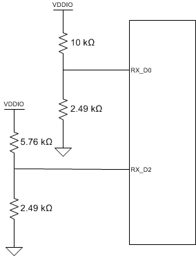
Refer to Figure 7-13 for an example of a PHY address connection to external components. In this example, the pins are configured as follows: RX_D2 = Strap Mode 3 and RX_D0 = Strap Mode 2. Therefore, the PHY address strapping results in address 1001 (09h).
 Figure 7-13 PHY Address Strapping Example
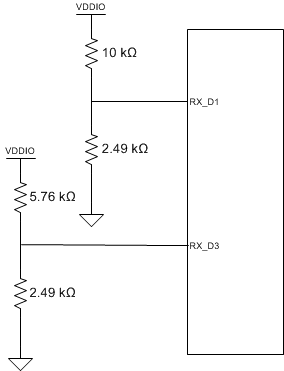
When operating in SGMII mode, dummy straps must be added to provide a balanced load for the SGMII differential pairs. Therefore, for SGMII applications with the straps shown in Figure 7-13, the corresponding connections for RX_D1 and RX_D3 are shown in Figure 7-14.
 Figure 7-14 PHY Address Strapping Example for SGMII