JAJSEN3G March 2012 – March 2018 DRV110
PRODUCTION DATA.
- 1 特長
- 2 アプリケーション
- 3 概要
- 4 改訂履歴
- 5 Pin Configuration and Functions
- 6 Specifications
- 7 Detailed Description
- 8 Application and Implementation
- 9 Power Supply Recommendations
- 10Layout
- 11デバイスおよびドキュメントのサポート
- 12メカニカル、パッケージ、および注文情報
パッケージ・オプション
メカニカル・データ(パッケージ|ピン)
サーマルパッド・メカニカル・データ
発注情報
7.3.3 Configuring Peak and Hold Currents
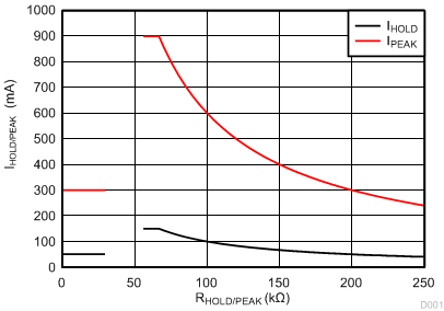
IPEAK and IHOLD depend on fixed resistance values RPEAK and RHOLD as shown in Figure 4. If the PEAK pin or HOLD pin is connected to ground or RPEAK or RHOLD is less than 43.33 kΩ (typical), then IPEAK is at its default value of 300 mA for IPEAK and 50 mA for IHOLD.
The IPEAK value can alternatively be set by connecting an external resistor to ground from the PEAK pin. For example, if a 60-kΩ (= RPEAK) resistor is connected between PEAK and GND, and RSENSE = 1 Ω, then the externally set IPEAK level will be 900 mA. If RPEAK = 200 kΩ and RSENSE = 1 Ω, then the externally set IPEAK level will be 300 mA. TI does not recommend using a resistor from 30 kΩ and 55 kΩ to avoid the IPEAK or IHOLD current slipping from the maximum current setting to the default setting.
In case RSENSE = 2 Ω instead of 1 Ω, then IPEAK = 450 mA (when RPEAK = 55 kΩ) and IPEAK = 150 mA (when RPEAK = 200 kΩ). In the 8-pin package, the HOLD reference uses the internal VREF setting of 50 mV. In the 14-pin package, external setting of the HOLD current, IHOLD, works in the same way as the external setting for IPEAK but the current levels are 1/6 of the IPEAK levels for the same resistor setting.
External settings for IPEAK and IHOLD are independent of each other. If RPEAK or RHOLD is decreased below 33.33 kΩ (typical value), then the reference is clamped to the internal setting of 300 mV for PEAK and 50 mV for HOLD. Use Equation 2 and Equation 3 to calculate the values for IPEAK and IHOLD respectively.
The currents and resistor values should be chosen such that the voltage across the sense resistor is more than 30 mV.


