JAJSKV6D August 2020 – April 2024 DRV8714-Q1 , DRV8718-Q1
PRODMIX
- 1
- 1 特長
- 2 アプリケーション
- 3 概要
- 4 Device Comparison Table
- 5 Pin Configuration and Functions
- 6 Specifications
-
7 Detailed Description
- 7.1 Overview
- 7.2 Functional Block Diagram
- 7.3
Feature Description
- 7.3.1 External Components
- 7.3.2 Device Interface Variants
- 7.3.3 Input PWM Control Modes
- 7.3.4 Smart Gate Driver
- 7.3.5 Tripler (Dual-Stage) Charge Pump
- 7.3.6 Wide Common-Mode Current Shunt Amplifiers
- 7.3.7 Pin Diagrams
- 7.3.8
Protection and Diagnostics
- 7.3.8.1 Gate Driver Disable (DRVOFF/nFLT and EN_DRV)
- 7.3.8.2 Low IQ Powered Off Braking (POB, BRAKE)
- 7.3.8.3 Fault Reset (CLR_FLT)
- 7.3.8.4 DVDD Logic Supply Power on Reset (DVDD_POR)
- 7.3.8.5 PVDD Supply Undervoltage Monitor (PVDD_UV)
- 7.3.8.6 PVDD Supply Overvoltage Monitor (PVDD_OV)
- 7.3.8.7 VCP Charge Pump Undervoltage Lockout (VCP_UV)
- 7.3.8.8 MOSFET VDS Overcurrent Protection (VDS_OCP)
- 7.3.8.9 Gate Driver Fault (VGS_GDF)
- 7.3.8.10 Thermal Warning (OTW)
- 7.3.8.11 Thermal Shutdown (OTSD)
- 7.3.8.12 Offline Short Circuit and Open Load Detection (OOL and OSC)
- 7.3.8.13 Watchdog Timer
- 7.3.8.14 Fault Detection and Response Summary Table
- 7.4 Device Functional Modes
- 7.5 Programming
- 8 Register Maps
- 9 Application Implementation
- 10Device Documentation and Support
- 11Revision History
- 12Mechanical, Packaging, and Orderable Information
パッケージ・オプション
メカニカル・データ(パッケージ|ピン)
サーマルパッド・メカニカル・データ
発注情報
7.3.3.3.1 DRV8714-Q1 Split HS and LS Solenoid Control
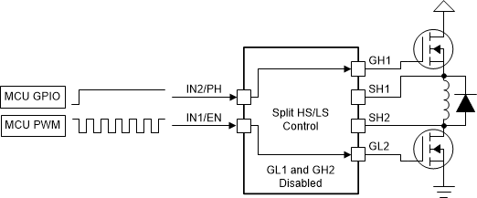
In split HS and LS solenoid control mode, the H-bridge pairs (1 / 2 and 3 / 4) are configured to simplify solenoid control schemes as shown in Figure 7-10. This mode allows for the H-bridge to be configured to drive a floating solenoid load between the opposite high-side and low-side external MOSFETs. The solenoid control mode can be enabled by setting the BRG_MODE control register to 11b on SPI interface variants and MODE pin to Level 4 on H/W interface variants..
The high-side MOSFET of the primary half-bridge acts as a HS disconnect switch (controlled through the INx/PHx pin or S_PHx control registers) and the low-side MOSFET of the secondary half-bridge acts as the PWM control for the solenoid (controlled through the INx/ENx pin or S_ENx control register. The INx/ENx and INx/PHx SPI control can be enabled through the INx/ENx_MODE and INx/PHx_MODE register settings. The primary half-bridge low-side MOSFET control is disabled and the secondary half-bridge high-side MOSFET control is disabled. The control truth table is shown in Table 7-13 and Table 7-14.
| IN1/EN1 | IN2/PH1 | GH1 | GL1 | GH2 | GL2 | DESCRIPTION |
|---|---|---|---|---|---|---|
| 0 | X | X | Inactive | Inactive | L | Solenoid PWM Off |
| 1 | X | X | Inactive | Inactive | H | Solenoid PWM On |
| X | 0 | L | Inactive | Inactive | X | Solenoid Disabled |
| X | 1 | H | Inactive | Inactive | X | Solenoid Enabled |
| IN3/EN2 | IN4/PH2 | GH3 | GL3 | GH4 | GL4 | DESCRIPTION |
|---|---|---|---|---|---|---|
| 0 | X | X | Inactive | Inactive | L | Solenoid PWM Off |
| 1 | X | X | Inactive | Inactive | H | Solenoid PWM On |
| X | 0 | L | Inactive | Inactive | X | Solenoid Disabled |
| X | 1 | H | Inactive | Inactive | X | Solenoid Enabled |
 Figure 7-10 Solenoid
Control Example