JAJSCF9A June 2015 – June 2015 FDC2112 , FDC2114 , FDC2212 , FDC2214
PRODUCTION DATA.
- 1 特長
- 2 アプリケーション
- 3 概要
- 4 改訂履歴
- 5 概要(続き)
- 6 デバイス比較表
- 7 ピン構成および機能
- 8 仕様
-
9 詳細説明
- 9.1 概要
- 9.2 機能ブロック図
- 9.3 機能説明
- 9.4 デバイスの機能モード
- 9.5 プログラミング
- 9.6
レジスタ・マップ
- 9.6.1 レジスタ一覧
- 9.6.2 アドレス0x00、DATA_CH0
- 9.6.3 アドレス0x01、DATA_LSB_CH0(FDC2212 / FDC2214のみ)
- 9.6.4 アドレス0x02、DATA_CH1
- 9.6.5 アドレス0x03、DATA_LSB_CH1(FDC2212 / FDC2214のみ)
- 9.6.6 アドレス0x04、DATA_CH2(FDC2114, FDC2214のみ)
- 9.6.7 アドレス0x05、DATA_LSB_CH2(FDC2214のみ)
- 9.6.8 アドレス0x06、DATA_CH3(FDC2114, FDC2214のみ)
- 9.6.9 アドレス0x07、DATA_LSB_CH3(FDC2214のみ)
- 9.6.10 アドレス0x08、RCOUNT_CH0
- 9.6.11 アドレス0x09、RCOUNT_CH1
- 9.6.12 アドレス0x0A、RCOUNT_CH2(FDC2114, FDC2214のみ)
- 9.6.13 アドレス0x0B、RCOUNT_CH3(FDC2114, FDC2214のみ)
- 9.6.14 アドレス0x0C、OFFSET_CH0(FDC2112 / FDC2114のみ)
- 9.6.15 アドレス0x0D、OFFSET_CH1(FDC2112 / FDC2114のみ)
- 9.6.16 アドレス0x0E、OFFSET_CH2(FDC2114のみ)
- 9.6.17 アドレス0x0F、OFFSET_CH3(FDC2114のみ)
- 9.6.18 アドレス0x10、SETTLECOUNT_CH0
- 9.6.19 アドレス0x11、SETTLECOUNT_CH1
- 9.6.20 アドレス0x12、SETTLECOUNT_CH2(FDC2114, FDC2214のみ)
- 9.6.21 アドレス0x13、SETTLECOUNT_CH3(FDC2114, FDC2214のみ)
- 9.6.22 アドレス0x14、CLOCK_DIVIDERS_CH0
- 9.6.23 アドレス0x15、CLOCK_DIVIDERS_CH1
- 9.6.24 アドレス0x16、CLOCK_DIVIDERS_CH2(FDC2114, FDC2214のみ)
- 9.6.25 アドレス0x17、CLOCK_DIVIDERS_CH3(FDC2114, FDC2214のみ)
- 9.6.26 アドレス0x18、STATUS
- 9.6.27 アドレス0x19、ERROR_CONFIG
- 9.6.28 アドレス0x1A、CONFIG
- 9.6.29 アドレス0x1B、MUX_CONFIG
- 9.6.30 アドレス0x1C、RESET_DEV
- 9.6.31 アドレス0x1E、DRIVE_CURRENT_CH0
- 9.6.32 アドレス0x1F、DRIVE_CURRENT_CH1
- 9.6.33 アドレス0x20、DRIVE_CURRENT_CH2(FDC2114 / FDC2214のみ)
- 9.6.34 アドレス0x21、DRIVE_CURRENT_CH3(FDC2114 / FDC2214のみ)
- 9.6.35 アドレス0x7E、MANUFACTURER_ID
- 9.6.36 アドレス0x7F、DEVICE_ID
- 10アプリケーションと実装
- 11電源に関する推奨事項
- 12レイアウト
- 13デバイスおよびドキュメントのサポート
- 14メカニカル、パッケージ、および注文情報
パッケージ・オプション
メカニカル・データ(パッケージ|ピン)
- RGH|16
サーマルパッド・メカニカル・データ
- RGH|16
発注情報
8 仕様
8.1 絶対最大定格
(1)| MIN | MAX | UNIT | ||
|---|---|---|---|---|
| VDD | Supply voltage range | 5 | V | |
| Vi | Voltage on any pin | –0.3 | VDD +0.3 | V |
| IA | Input current on any INx pin | –8 | 8 | mA |
| ID | Input current on any digital pin | –5 | 5 | mA |
| TJ | Junction temperature | –55 | 150 | °C |
| Tstg | Storage temperature | –65 | 150 | ℃ |
(1) 絶対最大定格を上回るストレスが加わった場合、デバイスに永続的な損傷が発生する可能性があります。これはストレスの定格のみについて示してあり、このデータシートの「推奨動作条件」に示された値を越える状態での本製品の機能動作は含まれていません。絶対最大定格の状態に長時間置くと、本製品の信頼性に影響を与えることがあります。
8.2 ESD定格
| VALUE | UNIT | |||
|---|---|---|---|---|
| FDC2112 / FDC2212 in 12-pin WSON package | ||||
| V(ESD) | Electrostatic discharge | Human-body model (HBM), per ANSI/ESDA/JEDEC JS-001(1) | ±2000 | V |
| Charged-device model (CDM), per JEDEC specification JESD22-C101(2) | ±750 | |||
| FDC2114 / FDC2214 in 16-pin WQFN package | ||||
| V(ESD) | Electrostatic discharge | Human-body model (HBM), per ANSI/ESDA/JEDEC JS-001(1) | ±2000 | V |
| Charged-device model (CDM), per JEDEC specification JESD22-C101(2) | ±750 | |||
(1) JEDECのドキュメントJEP155に、500V HBMでは標準のESD管理プロセスで安全な製造が可能であると規定されています。
(2) JEDECのドキュメントJEP157に、250V CDMでは標準のESD管理プロセスで安全な製造が可能であると規定されています。
8.3 推奨動作条件
特記のない限り、すべてのリミット値はTA=25℃、VDD=3.3Vに対して規定されています。| MIN | NOM | MAX | UNIT | ||
|---|---|---|---|---|---|
| VDD | Supply voltage | 2.7 | 3.6 | V | |
| TA | Operating temperature | –40 | 125 | °C | |
8.4 熱特性について
| THERMAL METRIC(1) | FDC2112 / FDC2212 | FDC2214 / FDC2214 | UNIT | |
|---|---|---|---|---|
| DNT (WSON) | RGH (WQFN) | |||
| 12 PINS | 16 PINS | |||
| RθJA | Junction-to-ambient thermal resistance | 50 | 38 | °C/W |
(1) 従来および新しい熱測定値の詳細については、半導体およびICパッケージの熱測定値のアプリケーション・レポートSPRA953を参照してください。
8.5 電気的特性
特記のない限り、すべてのリミット値はTA=25℃、VDD=3.3Vに対して規定されています。(1)| PARAMETER | TEST CONDITIONS(2) | MIN(3) | TYP(4) | MAX(3) | UNIT | |
|---|---|---|---|---|---|---|
| POWER | ||||||
| VDD | Supply voltage | TA = –40°C to +125°C | 2.7 | 3.6 | V | |
| IDD | Supply durrent (not including sensor current)(5) | CLKIN = 10MHz(6) | 2.1 | mA | ||
| IDDSL | Sleep mode supply current(5) | 35 | 60 | µA | ||
| ISD | Shutdown mode supply current(5) | 0.2 | 1 | µA | ||
| CAPACITIVE SENSOR | ||||||
| CSENSORMAX | Maximum sensor capacitance | 1mH inductor, 10kHz oscillation | 250 | nF | ||
| CIN | Sensor pin parasitic capacitance | 4 | pF | |||
| NBITS | Number of bits | FDC2112, FDC2114 RCOUNT ≥ 0x0400 |
12 | bits | ||
| FDC2212, FDC2214 RCOUNT = 0xFFFF |
28 | bits | ||||
| fCS | Maximum channel sample rate | FDC2112, FDC2114 single active channel continuous conversion, SCL = 400 kHz |
13.3 | kSPS | ||
| FDC2212, FDC2214 single active channel continuous conversion, SCL= 400 kHz |
4.08 | kSPS | ||||
| EXCITATION | ||||||
| fSENSOR | Sensor excitation frequency | TA = –40°C to +125°C | 0.01 | 10 | MHz | |
| VSENSORMIN | Minimum sensor oscillation amplitude (pk)(7) | 1.2 | V | |||
| VSENSORMAX | Maximum sensor oscillation amplitude (pk) | 1.8 | V | |||
| ISENSORMAX | Sensor maximum current drive | HIGH_CURRENT_DRV = b0 DRIVE_CURRENT_CH0 = 0xF800 |
1.5 | mA | ||
| HIGH_CURRENT_DRV = b1 DRIVE_CURRENT_CH0 = 0xF800 Channel 0 only |
6 | mA | ||||
| MASTER CLOCK | ||||||
| fCLKIN | External master clock input frequency (CLKIN) | TA = –40°C to +125°C | 2 | 40 | MHz | |
| CLKINDUTY_MIN | External master clock minimum acceptable duty cycle (CLKIN) | 40% | ||||
| CLKINDUTY_MAX | External master clock maximum acceptable duty cycle (CLKIN) | 60% | ||||
| VCLKIN_LO | CLKIN low voltage threshold | 0.3*VDD | V | |||
| VCLKIN_HI | CLKIN high voltage threshold | 0.7*VDD | V | |||
| fINTCLK | Internal master clock frequency range | 35 | 43.4 | 55 | MHz | |
| TCf_int_μ | Internal master clock temperature coefficient mean | –13 | ppm/°C | |||
(1) 「電気的特性」の値は、記載温度における工場出荷試験条件にのみ適用されます。工場試験条件で生ずる自己発熱は、TJ=TAとなる程度にきわめてわずかです。「電気的特性」には、自己発熱によりTJ>TAとなる条件下で保証されるパラメータ性能値は記載されていません。「絶対最大定格」に記載されている接合部温度上限を超えるとデバイスに物理的または電気的な恒久的損傷を与えるおそれがあります。
(2) レジスタ値は、2進数(接頭辞がb)または16進数(接頭辞が0x)で表記されています。10進値には接頭辞はありません。
(3) 25℃でのリミット値は試験、設計、または統計解析により規定されています。全動作温度範囲におけるリミット値は標準統計品質管理(SQC)法によって決められた補正データを加味して規定されています。
(4) 標準(typ)値は、特性評価時におけるパラメータの基準値(norm)を表します。実際の標準値は、経時的に変化するとともに、アプリケーションや構成にも依存します。これらの標準値はテストされた値ではなく、出荷済みの製品材料に対する保証値ではありません。
(5) SCL、SDAを流れるI2C読み取り/書き込み通信電流およびプルアップ抵抗電流は含みません。
(6) センサ・コンデンサ: 1層、20.9 x 13.9mm、Bourns CMH322522-180KLセンサ・インダクタ、L=18µHおよび33pF 1% COG/NP0、ターゲット: 接地アルミニウム・プレート(176 x 123mm)、チャネル = チャネル0(連続モード)、CLKIN = 40MHz、CHx_FIN_SEL = b10、CHx_FREF_DIVIDER = b00 0000 0001、CH0_RCOUNT = 0xFFFF、SETTLECOUNT_CH0 = 0x0100、DRIVE_CURRENT_CH0 = 0x7800
(7) より小さいVSENSORMIN発振振幅も使用できますが、SNRは低下します。
8.6 タイミング要件
| MIN | NOM | MAX | UNIT | ||
|---|---|---|---|---|---|
| tSDWAKEUP | Wake-up time from SD high-low transition to I2C readback | 2 | ms | ||
| tSLEEPWAKEUP | Wake-up time from sleep mode | 0.05 | ms | ||
| tWD-TIMEOUT | Sensor recovery time (after watchdog timeout) | 5.2 | ms | ||
| I2C TIMING CHARACTERISTICS | |||||
| fSCL | Clock frequency | 10 | 400 | kHz | |
| tLOW | Clock low time | 1.3 | μs | ||
| tHIGH | Clock high time | 0.6 | μs | ||
| tHD;STA | Hold time (repeated) START condition: after this period, the first clock pulse is generated | 0.6 | μs | ||
| tSU;STA | Setup time for a repeated START condition | 0.6 | μs | ||
| tHD;DAT | Data hold time | 0 | μs | ||
| tSU;DAT | Data setup time | 100 | ns | ||
| tSU;STO | Setup time for STOP condition | 0.6 | μs | ||
| tBUF | Bus free time between a STOP and START condition | 1.3 | μs | ||
| tVD;DAT | Data valid time | 0.9 | μs | ||
| tVD;ACK | Data valid acknowledge time | 0.9 | μs | ||
| tSP | Pulse width of spikes that must be suppressed by the input filter(1) | 50 | ns | ||
 Figure 1. I2Cのタイミング
8.7 スイッチング特性 - I2C
特記のない限り、すべてのリミット値はTA=25℃、VDD=3.3Vに対して規定されています。| PARAMETER | TEST CONDITIONS | MIN | TYP | MAX | UNIT | |
|---|---|---|---|---|---|---|
| VOLTAGE LEVELS | ||||||
| VIH | Input high voltage | 0.7ˣVDD | V | |||
| VIL | Input low voltage | 0.3ˣVDD | V | |||
| VOL | Output low voltage (3 mA sink current) | 0.4 | V | |||
| HYS | Hysteresis | 0.1ˣVDD | V | |||
(1) このパラメータは設計および特性で規定される値であり、実製品のテストは行っていません。
8.8 代表的特性
共通テスト条件(特に注記のない場合): センサ・コンデンサ: 1層、20.9 x 13.9mm、Bourns CMH322522-180KLセンサ・インダクタ、L=18µHおよび33pF 1% COG/NP0、ターゲット: 接地アルミニウム・プレート(176 x 123mm)、チャネル = チャネル0(連続モード)、CLKIN = 40MHz、CHx_FIN_SEL = b01、CHx_FREF_DIVIDER = b00 0000 0001、CH0_RCOUNT = 0xFFFF、SETTLECOUNT_CH0 = 0x0100、DRIVE_CURRENT_CH0 = 0x7800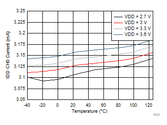
| Includes 1.57 mA sensor current | ||
| –40℃~+125℃ |
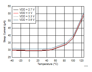
| –40℃~+125℃ |
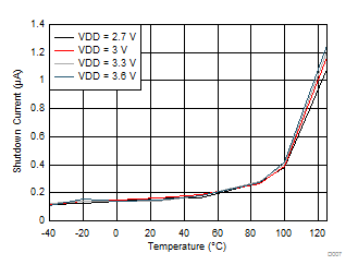
| –40℃~+125℃ |
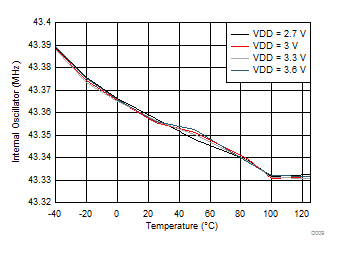
| –40℃~+125℃ | ||
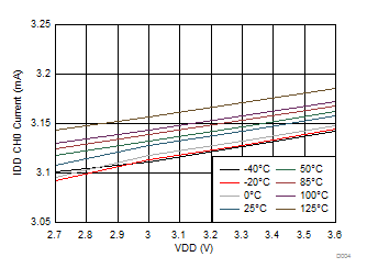
| Includes 1.57 mA sensor current | ||
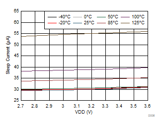
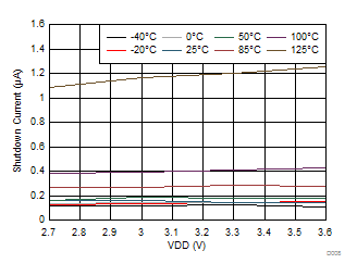
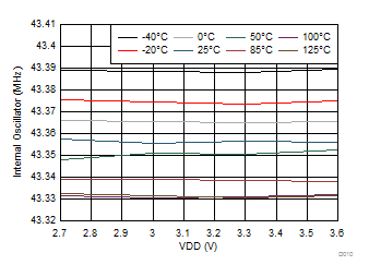
| Data based on 1 unit | ||