JAJSF29A December 2014 – March 2018 LDC1312 , LDC1314
PRODUCTION DATA.
- 1 特長
- 2 アプリケーション
- 3 概要
- 4 改訂履歴
- 5 Pin Configuration and Functions
- 6 Specifications
-
7 Detailed Description
- 7.1 Overview
- 7.2 Functional Block Diagram
- 7.3 Feature Description
- 7.4 Device Functional Modes
- 7.5 Programming
- 7.6
Register Maps
- 7.6.1 Register List
- 7.6.2 Address 0x00, DATA0
- 7.6.3 Address 0x02, DATA1
- 7.6.4 Address 0x04, DATA2 (LDC1314 only)
- 7.6.5 Address 0x06, DATA3 (LDC1314 only)
- 7.6.6 Address 0x08, RCOUNT0
- 7.6.7 Address 0x09, RCOUNT1
- 7.6.8 Address 0x0A, RCOUNT2 (LDC1314 only)
- 7.6.9 Address 0x0B, RCOUNT3 (LDC1314 only)
- 7.6.10 Address 0x0C, OFFSET0
- 7.6.11 Address 0x0D, OFFSET1
- 7.6.12 Address 0x0E, OFFSET2 (LDC1314 only)
- 7.6.13 Address 0x0F, OFFSET3 (LDC1314 only)
- 7.6.14 Address 0x10, SETTLECOUNT0
- 7.6.15 Address 0x11, SETTLECOUNT1
- 7.6.16 Address 0x12, SETTLECOUNT2 (LDC1314 only)
- 7.6.17 Address 0x13, SETTLECOUNT3 (LDC1314 only)
- 7.6.18 Address 0x14, CLOCK_DIVIDERS0
- 7.6.19 Address 0x15, CLOCK_DIVIDERS1
- 7.6.20 Address 0x16, CLOCK_DIVIDERS2 (LDC1314 only)
- 7.6.21 Address 0x17, CLOCK_DIVIDERS3 (LDC1314 only)
- 7.6.22 Address 0x18, STATUS
- 7.6.23 Address 0x19, ERROR_CONFIG
- 7.6.24 Address 0x1A, CONFIG
- 7.6.25 Address 0x1B, MUX_CONFIG
- 7.6.26 Address 0x1C, RESET_DEV
- 7.6.27 Address 0x1E, DRIVE_CURRENT0
- 7.6.28 Address 0x1F, DRIVE_CURRENT1
- 7.6.29 Address 0x20, DRIVE_CURRENT2 (LDC1314 only)
- 7.6.30 Address 0x21, DRIVE_CURRENT3 (LDC1314 only)
- 7.6.31 Address 0x7E, MANUFACTURER_ID
- 7.6.32 Address 0x7F, DEVICE_ID
-
8 Application and Implementation
- 8.1
Application Information
- 8.1.1 Conductive Objects in a Time-Varying EM Field
- 8.1.2 L-C Resonators
- 8.1.3 Multi-Channel and Single Channel Operation
- 8.1.4 Sensor Conversion Time
- 8.1.5 Sensor Current Drive Configuration
- 8.1.6 Clocking Architecture
- 8.1.7 Input Deglitch Filter
- 8.1.8 Device Status Registers
- 8.1.9 Multi-Channel Data Readback
- 8.2 Typical Application
- 8.1
Application Information
- 9 Power Supply Recommendations
- 10Layout
- 11デバイスおよびドキュメントのサポート
- 12メカニカル、パッケージ、および注文情報
パッケージ・オプション
メカニカル・データ(パッケージ|ピン)
- RGH|16
サーマルパッド・メカニカル・データ
- RGH|16
発注情報
8.1.3.2 Digital Signal Gain
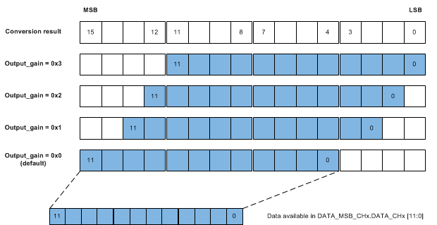
Internally, the LDC measures inductance shifts with 16 bits of resolution, while the conversion output word width is only 12 bits. For systems in which the sensor signal variation is less than 25% of the full scale range, the LDC can report conversion results with higher resolution by setting the Output Gain. The Output Gain is applied to all device channels. An output gain can be used to apply a 2-bit, 3-bit, or 4-bit shift to the output code for all channels, providing an effectively higher measurement resolution. When the Gain function is used, additional LSBs of the conversion word are reported, while the corresponding number of MSBs are not reported.
To avoid data corruption issues, use the Output Gain function (Data Offset) to shift the output codes to prevent toggling of the shifted MSBs.
Table 35. Output Gain Register
| CHANNEL(1) | REGISTER | FIELD [ BIT(S) ] | VALUES | EFFECTIVE RESOLUTION (BITS) | OUTPUT RANGE |
|---|---|---|---|---|---|
| All | RESET_DEV, addr 0x1C | OUTPUT_GAIN [ 10:9 ] | 00 (default): Gain =1 (0 bits shift) | 12 | 100% full scale |
| 01: Gain = 4 (2 bits left shift) | 14 | 25% full scale | |||
| 10: Gain = 8 (3 bits left shift) | 15 | 12.5% full scale | |||
| 11 : Gain = 16 (4 bits left shift) | 16 | 6.25% full scale |
Example: If the conversion result for a channel is 0x07A3, with OUTPUT_GAIN=0x0, the reported output code is 0x07A. If OUTPUT_GAIN is set to 0x3 in the same condition, then the reported output code is 0x7A3. The original 4 MSBs (0x0) are no longer accessible. Figure 51 illustrates the segments of the 16-bit sample that is reported for each possible gain setting.
 Figure 51. Conversion Data Output Gain