-
LM22675/-Q1 42 V, 1 A SIMPLE SWITCHER Step-Down Voltage Regulator with Features
- 1 Features
- 2 Applications
- 3 Description
- 4 Revision History
- 5 Pin Configuration and Functions
- 6 Specifications
- 7 Detailed Description
- 8 Application and Implementation
- 9 Power Supply Recommendations
- 10Layout
- 11Device and Documentation Support
- 12Mechanical, Packaging, and Orderable Information
- IMPORTANT NOTICE
LM22675/-Q1 42 V, 1 A SIMPLE SWITCHER Step-Down Voltage Regulator with Features
1 Features
- Wide Input Voltage Range: 4.5 V to 42 V
- Internally Compensated Voltage Mode Control
- Stable with Low ESR Ceramic Capacitors
- 200 mΩ N-Channel MOSFET
- Output Voltage Options:
-ADJ (Outputs as Low as 1.285 V)
-5.0 (Output Fixed to 5 V) - ±1.5% Feedback Reference Accuracy
- Switching Frequency of 500 kHz
- –40°C to 125°C Operating Junction Temperature Range
- Precision Enable Pin
- Integrated Boot-Strap Diode
- Integrated Soft-Start
- Fully WEBENCH® Enabled
- Step-Down and Inverting Buck-Boost Applications
- LM22675Q is an Automotive Grade Product
that is AEC-Q100 Grade 1 Qualified (–40°C to +125°C Operating Junction Temperature) - SO PowerPAD-8 (Exposed Pad) Package
2 Applications
- Industrial Control
- Telecom and Datacom Systems
- Embedded Systems
- Conversions from Standard 24 V, 12 V and 5 V Input Rails
3 Description
The LM22675 switching regulator provides all of the functions necessary to implement an efficient high voltage step-down (buck) regulator using a minimum of external components. This easy to use regulator incorporates a 42 V N-channel MOSFET switch capable of providing up to 1 A of load current. Excellent line and load regulation along with high efficiency (> 90%) are featured. Voltage mode control offers short minimum on-time, allowing the widest ratio between input and output voltages. Internal loop compensation means that the user is free from the tedious task of calculating the loop compensation components. Fixed 5 V output and adjustable output voltage options are available. A switching frequency of 500 kHz allows for small external components and good transient response. A precision enable input allows simplification of regulator control and system power sequencing. In shutdown mode the regulator draws only 25 µA (typ). Built in soft-start (500 µs, typ) saves external components. The LM22675 also has built in thermal shutdown, and current limiting to protect against accidental overloads.
The LM22675 is a member of Texas Instruments' SIMPLE SWITCHER® family. The SIMPLE SWITCHER concept provides for an easy to use complete design using a minimum number of external components and the TI WEBENCH design tool. TI's WEBENCH tool includes features such as external component calculation, electrical simulation, thermal simulation, and Build-It boards for easy design-in.
Device Information(1)
| PART NUMBER | PACKAGE | BODY SIZE (NOM) |
|---|---|---|
| LM22675 | HSOP (8) | 4.89 mm x 3.90 mm |
| LM22675-Q1 |
- For all available packages, see the orderable addendum at the end of the data sheet.
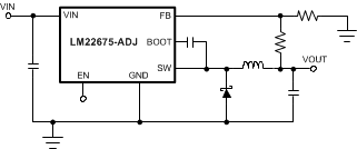
Simplified Application Schematic

4 Revision History
Changes from K Revision (March 2013) to L Revision
- Added LM22675-Q1 part number. Go
- Added Pin Configuration and Functions section, Handling Rating table, Feature Description section, Device Functional Modes, Application and Implementation section, Power Supply Recommendations section, Layout section, Device and Documentation Support section, and Mechanical, Packaging, and Orderable Information section Go
- Deleted Inverting Regulator ApplicationGo
5 Pin Configuration and Functions

Pin Functions
| PIN | TYPE | DESCRIPTION | APPLICATION INFORMATION | |
|---|---|---|---|---|
| NAME | NO. | |||
| BOOT | 1 | I | Bootstrap input | Provides the gate voltage for the high side NFET. |
| EN | 5 | I | Enable Input | Used to control regulator start-up and shutdown. See Precision Enable section of data sheet. |
| EP | EP | — | Exposed Pad | Connect to ground. Provides thermal connection to PCB. See Application and Implementation. |
| FB | 4 | I | Feedback pin | Feedback input to regulator. |
| GND | 6 | — | Ground input to regulator; system common | System ground pin. |
| NC | 2, 3 | — | Not Connected | Pins are not electrically connected inside the chip. Pins do function as thermal conductor. |
| SW | 8 | O | Switch pin | Switching output of regulator |
| VIN | 7 | I | Input Voltage | Input supply to regulator |