-
LM2734x/LM2734x-Q1 2MHz、1.5A/2A、広い入力電圧範囲の降圧型DC/DCレギュレータ、周波数同期機能搭載 JAJSAQ9F November 2008 – September 2016 LM27341 , LM27341-Q1 , LM27342 , LM27342-Q1
PRODUCTION DATA.
-
LM2734x/LM2734x-Q1 2MHz、1.5A/2A、広い入力電圧範囲の降圧型DC/DCレギュレータ、周波数同期機能搭載
- 1 特長
- 2 アプリケーション
- 3 概要
- 4 改訂履歴
- 5 Pin Configuration and Functions
- 6 Specifications
- 7 Detailed Description
-
8 Application and Implementation
- 8.1
Application Information
- 8.1.1 Inductor Selection
- 8.1.2 Inductor Material Selection
- 8.1.3 Input Capacitor
- 8.1.4 Output Capacitor
- 8.1.5 Catch Diode
- 8.1.6 Boost Diode (Optional)
- 8.1.7 Boost Capacitor
- 8.1.8 Output Voltage
- 8.1.9 Feedforward Capacitor (Optional)
- 8.1.10
Calculating Efficiency and Junction Temperature
- 8.1.10.1 Schottky Diode Conduction Losses
- 8.1.10.2 Inductor Conduction Losses
- 8.1.10.3 MOSFET Conduction Losses
- 8.1.10.4 MOSFET Switching Losses
- 8.1.10.5 IC Quiescent Losses
- 8.1.10.6 MOSFET Driver Losses
- 8.1.10.7 Total Power Losses
- 8.1.10.8 Efficiency Calculation Example
- 8.1.10.9 Calculating Junction Temperature
- 8.2
Typical Applications
- 8.2.1 LM2734x Configuration From VIN = 7 V to 16 V, VOUT = 5 V For Full Load at 2 MHz
- 8.2.2 LM2734x Configuration From VIN = 7 V to 16 V, VOUT = 5 V For Full Load at 1 MHz
- 8.2.3 LM2734x Configuration From VIN = 5 V to 16 V, VOUT = 3.3 V For Full Load at 2 MHz
- 8.2.4 LM2734x Configuration From VIN = 5 V to 16 V, VOUT = 3.3 V For Full Load at 2 MHz With SYNC = GND
- 8.2.5 LM2734x Configuration From VIN = 5 V to 16 V, VOUT = 3.3 V For Full Load at 2 MHz With SYNC = 1 MHz
- 8.2.6 LM2734x Configuration From VIN = 3.3 V to 16 V, VOUT = 1.8 V For Full Load at 2 MHz With SYNC = 1 GND
- 8.2.7 LM2734x Configuration From VIN = 3.3 V to 16 V, VOUT = 1.8 V For Full Load at 2 MHz With SYNC = 1 MHz
- 8.2.8 LM2734x Configuration From VIN = 3.3 V to 9 V, VOUT = 1.2 V For Full Load at 2 MHz With SYNC = 2 MHz
- 8.1
Application Information
- 9 Power Supply Recommendations
- 10Layout
- 11デバイスおよびドキュメントのサポート
- 12メカニカル、パッケージ、および注文情報
- 重要なお知らせ
パッケージ・オプション
メカニカル・データ(パッケージ|ピン)
- DGQ|10
サーマルパッド・メカニカル・データ
- DGQ|10
発注情報
LM2734x/LM2734x-Q1 2MHz、1.5A/2A、広い入力電圧範囲の降圧型DC/DCレギュレータ、周波数同期機能搭載
1 特長
- 省スペースの3mm×3mm 10ピンWSONおよびMSOP-PowerPADパッケージ
- 広い入力電圧範囲: 3V~20V
- 広い出力電圧範囲: 1V~18V
- LM27341は最大1.5Aの出力電流を供給
- LM27342は最大2Aの出力電流を供給
- 高いスイッチング周波数: 2MHz
- 周波数同期:
1MHz < fSW < 2.35MHz - 内部的なブートストラップ電源付きの150mΩ NMOSスイッチ
- シャットダウン電流: 70nA
- 精度1%の内部基準電圧
- ピーク電流モード、PWM動作
- サーマル・シャットダウン
- LM27341-Q1およびLM27342-Q1はAEC-Q100グレード1認定済みで、車載グレードのフローで製造
2 アプリケーション
- 12VからVcoreへの局所的な降圧型コンバータ
- 無線用電源
- HDDのコア電源
- セットトップ・ボックス
- 車載
- USB電力駆動のデバイス
- DSLモデム
3 概要
LM2734xおよびLM2734x-Q1レギュレータは、モノリシックな高周波数のPWM降圧型DC/DCコンバータで、10ピンのWSONと10ピンのMSOP-PowerPADパッケージで供給されます。局所的なDC/DC変換を高速な過渡応答および正確なレギュレーションとともに、可能な限り小さなPCB面積で実現するために必要な、すべてのアクティブ機能が搭載されています。
LM2734xおよびLM2734x-Q1は、最小限の外付け部品だけで簡単に使用できます。それぞれ1.5Aと2Aの負荷を駆動する能力を持ち、内部の150mΩ NMOSスイッチにより、利用可能な最高の電力密度を実現します。世界最高クラスの制御回路により、オン時間を65nsまで減らすことが可能で、非常に高い周波数での変換をサポートします。スイッチング周波数は内部的に2MHzに設定され、1~2.35MHzの範囲内で同期可能なため、非常に小さな表面実装のコイルとチップ・コンデンサを使用できます。動作周波数が非常に高いにもかかわらず、90%までの高い効率を簡単に実現できます。外部からのシャットダウン機能が搭載されており、70nAという非常に低いシャットダウン電流で動作します。LM2734xおよびLM2734x-Q1は、ピーク電流モード制御と内部的な補償によって、広範な動作条件において高性能のレギュレーションを実現します。追加機能として、内部的なソフトスタート回路による突入電流の低減、パルス単位の電流制限、サーマル・シャットダウン、出力過電圧保護が搭載されています。
製品情報(1)
| 型番 | パッケージ | 本体サイズ(公称) |
|---|---|---|
| LM2734x LM2734x-Q1 |
MSOP-PowerPAD (10) | 4.90mm×3.00mm |
| WSON (10) | 3.00mm×3.00mm |
- 提供されているすべてのパッケージについては、データシートの末尾にある注文情報を参照してください。
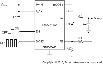
代表的なアプリケーション回路

4 改訂履歴
Changes from E Revision (April 2013) to F Revision
- 「ESD定格」表、「機能説明」セクション、「デバイスの機能モード」セクション、「アプリケーションと実装」セクション、「電源に関する推奨事項」セクション、「レイアウト」セクション、「デバイスおよびドキュメントのサポート」セクション、「メカニカル、パッケージ、および注文情報」セクションを追加Go
- Changed values in the Thermal Information table to align with JEDEC standardsGo
Changes from D Revision (April 2013) to E Revision
- Changed ナショナル・セミコンダクターのデータシートのレイアウトをTIフォーマットへGo
5 Pin Configuration and Functions
Pin Functions
| PIN | TYPE(1) | DESCRIPTION | |
|---|---|---|---|
| NO. | NAME | ||
| 1, 2 | SW | O | Output switch. Connects to the inductor, catch diode, and bootstrap capacitor. |
| 3 | BOOST | I | Boost voltage that drives the internal NMOS control switch. A bootstrap capacitor is connected between the BOOST and SW pins. |
| 4 | EN | I | Enable control input. Logic high enables operation. Do not allow this pin to float or be greater than VIN + 0.3 V. |
| 5 | SYNC | I | Frequency synchronization input. Drive this pin with an external clock or pulse train. Ground it to use the internal clock. |
| 6 | FB | I | Feedback pin. Connect FB to the external resistor divider to set output voltage. |
| 7 | GND | G | Signal and power ground pin. Place the bottom resistor of the feedback network as close as possible to this pin for accurate regulation. |
| 8 | AVIN | I | Supply voltage for the control circuitry. |
| 9, 10 | PVIN | I | Supply voltage for output power stage. Connect a bypass capacitor to this pin. |
| DAP | DAP | G | Signal or power ground and thermal connection. Tie this directly to GND (pin 7). See Application Information regarding optimum thermal layout. |