JAJSA67I April   2004  – February 2019 LM2743

PRODUCTION DATA.  

  1. 特長
  2. アプリケーション
  3. 概要
    1.     Device Images
      1.      代表的なアプリケーションの図
  4. 改訂履歴
  5. 概要(続き)
  6. Pin Configuration and Functions
    1.     Pin Functions
  7. Specifications
    1. 7.1 Absolute Maximum Ratings
    2. 7.2 ESD Ratings
    3. 7.3 Recommended Operating Conditions
    4. 7.4 Thermal Information
    5. 7.5 Electrical Characteristics
    6. 7.6 Typical Characteristics
  8. Detailed Description
    1. 8.1 Overview
    2. 8.2 Functional Block Diagram
    3. 8.3 Feature Description
      1. 8.3.1  Start Up and Soft-Start
      2. 8.3.2  Normal Operation
      3. 8.3.3  Tracking a Voltage Level
      4. 8.3.4  Tracking Voltage Slew Rate
      5. 8.3.5  Sequencing
      6. 8.3.6  SD Pin Impedance
      7. 8.3.7  MOSFET Gate Drivers
      8. 8.3.8  Power Good Signal
      9. 8.3.9  UVLO
      10. 8.3.10 Current Limit
      11. 8.3.11 Foldback Current Limit
    4. 8.4 Device Functional Modes
      1. 8.4.1 Shutdown
  9. Application and Implementation
    1. 9.1 Application Information
    2. 9.2 Typical Applications
      1. 9.2.1 Synchronous Buck Converter Typical Application using LM2743
        1. 9.2.1.1 Design Requirements
        2. 9.2.1.2 Detailed Design Procedure
          1. 9.2.1.2.1 Custom Design With WEBENCH® Tools
          2. 9.2.1.2.2 Duty Cycle Calculation
          3. 9.2.1.2.3 Input Capacitor
          4. 9.2.1.2.4 Output Inductor
          5. 9.2.1.2.5 Output Capacitor
          6. 9.2.1.2.6 MOSFETs
          7. 9.2.1.2.7 Support Components
          8. 9.2.1.2.8 Control Loop Compensation
          9. 9.2.1.2.9 Efficiency Calculations
        3. 9.2.1.3 Application Curves
      2. 9.2.2 Example Circuit 1
        1. 9.2.2.1 Design Requirements
        2. 9.2.2.2 Detailed Design Procedure
        3. 9.2.2.3 Bill of Materials
      3. 9.2.3 Example Circuit 2
        1. 9.2.3.1 Design Requirements
        2. 9.2.3.2 Detailed Design Procedure
        3. 9.2.3.3 Bill of Materials
      4. 9.2.4 Example Circuit 3
        1. 9.2.4.1 Design Requirements
        2. 9.2.4.2 Detailed Design Procedure
        3. 9.2.4.3 Bill of Materials
  10. 10Power Supply Recommendations
  11. 11Layout
    1. 11.1 Layout Guidelines
    2. 11.2 Layout Example
  12. 12デバイスおよびドキュメントのサポート
    1. 12.1 デバイス・サポート
      1. 12.1.1 開発サポート
        1. 12.1.1.1 WEBENCH®ツールによるカスタム設計
    2. 12.2 ドキュメントの更新通知を受け取る方法
    3. 12.3 コミュニティ・リソース
    4. 12.4 商標
    5. 12.5 静電気放電に関する注意事項
    6. 12.6 Glossary
  13. 13メカニカル、パッケージ、および注文情報

パッケージ・オプション

メカニカル・データ(パッケージ|ピン)
サーマルパッド・メカニカル・データ
発注情報

Typical Characteristics

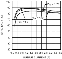
LM2743 20095240.gif
VCC = 3.3 V fSW = 300 kHz
Figure 1. Efficiency VOUT = 1.2 V
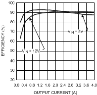
LM2743 20095241.gif
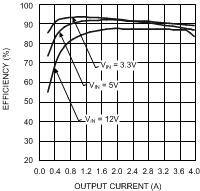
VCC = 5 V fSW = 300 kHz
Figure 3. Efficiency VOUT = 3.3 V
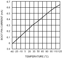
LM2743 20095242.gif
fSW = 300 kHz FDS6898A FET No-Load
Figure 5. BOOT Pin Current vs Temperature for BOOT Voltage = 3.3 V
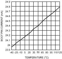
LM2743 20095244.gif
fSW = 300 kHz FDS6898A FET No-Load
Figure 7. BOOT Pin Current vs Temperature for BOOT Voltage = 12 V
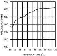
LM2743 20095260.gif
Figure 9. Frequency vs Temperature
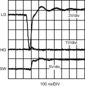
LM2743 20095246.gif
VCC = 3.3 V VIN = 5 V VOUT = 1.2 V
IOUT = 4 A CSS = 12 nF fSW = 300 kHz
Figure 11. Switch Waveforms (HG Rising)
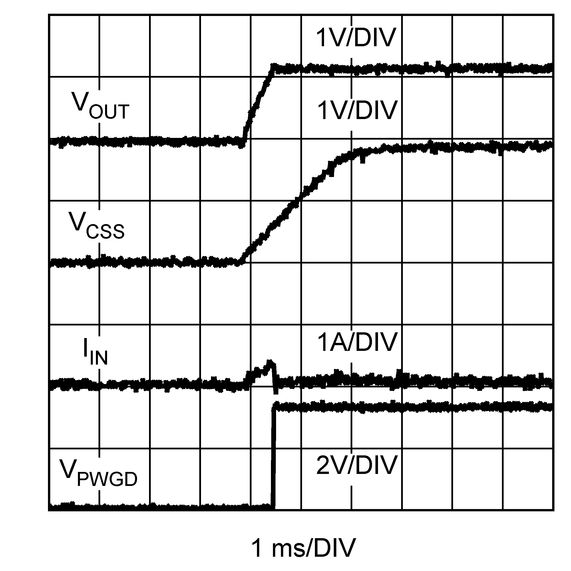
LM2743 20095248.png
VCC = 3.3 V VIN = 5V VOUT = 1.2V
CSS = 12 nF fSW = 300 kHz
Figure 13. Start-Up (No-Load)
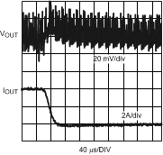
LM2743 20095252.gif
IOUT = 4 A to 0 A VCC = 3.3 V VIN = 5 V
VOUT = 1.2 V CSS = 12 nF fSW = 300 kHz
Figure 15. Load Transient Response
LM2743 20095254.gif
VIN = 3 V to 9 V VCC = 3.3 V VOUT = 1.2 V
Line () , IOUT = 2 A fSW = 300 kHz
Figure 17. Line Transient Response
LM2743 20095257.gif
VCC = 3.3 V fSW = 300 kHz
Figure 2. Efficiency VOUT = 2.5 V
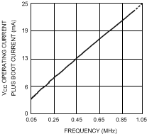
LM2743 20095245.gif
FDS6898A FET TA = 25°C
Figure 4. VCC Operating Current Plus BOOT Current vs Frequency
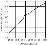
LM2743 20095243.gif
fSW = 300 kHz FDS6898A FET No-Load
Figure 6. BOOT Pin Current vs Temperature for BOOT Voltage = 5 V
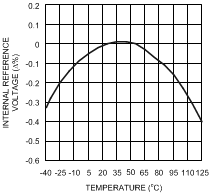
LM2743 20095258.gif
Figure 8. Internal Reference Voltage vs Temperature
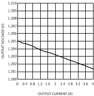
LM2743 20095256.gif
Figure 10. Output Voltage vs Output Current
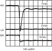
LM2743 20095247.gif
VCC = 3.3 V VIN = 5 V VOUT = 1.2 V
IOUT = 4 A CSS = 12 nF fSW = 300 kHz
Figure 12. Switch Waveforms (HG Falling)
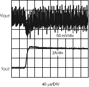
LM2743 20095251.gif
IOUT = 0 A to 4 A VCC = 3.3 V VIN = 5 V
VOUT = 1.2 V CSS = 12nF fSW = 300 kHz
Figure 14. Load Transient Response
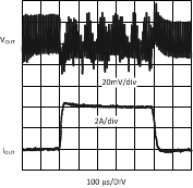
LM2743 20095253.gif
VCC = 3.3 V VIN = 5 V VOUT = 1.2 V
CSS = 12 nF fSW = 300 kHz
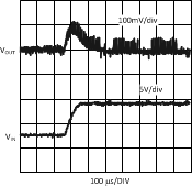
Figure 16. Load Transient Response
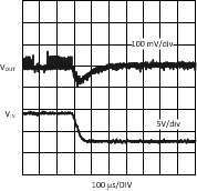
LM2743 20095255.gif
VIN = 9 V to 3 V VCC = 3.3 V VOUT = 1.2 V
IOUT = 2 A fSW = 300 kHz
Figure 18. Transient Response