JAJSAM0A October 2006 – September 2017 LM2853
PRODUCTION DATA.
- 1 特長
- 2 アプリケーション
- 3 概要
- 4 改訂履歴
- 5 Pin Configuration and Functions
- 6 Specifications
- 7 Detailed Description
-
8 Application and Implementation
- 8.1
Application Information
- 8.1.1 Input Capacitor (CIN)
- 8.1.2 Soft-Start Capacitor (CSS)
- 8.1.3 Soft-Start Capacitor (CSS) and Fault Conditions
- 8.1.4 Compensation
- 8.1.5 Output Filter Values
- 8.1.6 Choosing an Inductance Value
- 8.1.7 Output Filter Inductors
- 8.1.8 Output Filter Capacitors
- 8.1.9 Split-Rail Operation
- 8.1.10 Switch Node Protection
- 8.2 Typical Application
- 8.1
Application Information
- 9 Layout
- 10デバイスおよびドキュメントのサポート
- 11メカニカル、パッケージ、および注文情報
パッケージ・オプション
メカニカル・データ(パッケージ|ピン)
- PWP|14
サーマルパッド・メカニカル・データ
- PWP|14
発注情報
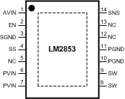
5 Pin Configuration and Functions
PWP
14-HTSSOP
Top View

Pin Functions
| NO. | NAME | DESCRIPTION |
|---|---|---|
| 1 | AVIN | Input Voltage for Control Circuitry |
| 2 | EN | Enable |
| 3 | SGND | Low noise ground |
| 4 | SS | Soft-Start Pin |
| 5 | NC | No Connect. This pin must be tied to ground. |
| 6,7 | PVIN | Input Voltage for Power Circuitry |
| 8,9 | SW | Switch Pin |
| 10,11 | PGND | Power Ground |
| 12,13 | NC | No-Connect. These pins must be tied to ground. |
| 14 | SNS | Output Voltage Sense Pin |
| Exposed Pad | EP | The exposed pad is internally connected to GND, but it cannot be used as the primary GND connection. The exposed pad should be soldered to an external GND plane. |