JAJSAY1E March 2008 – October 2017 LM2854
PRODUCTION DATA.
- 1 特長
- 2 アプリケーション
- 3 概要
- 4 改訂履歴
- 5 Pin Configuration and Functions
- 6 Specifications
- 7 Detailed Description
-
8 Application and Implementation
- 8.1 Application Information
- 8.2
Typical Application
- 8.2.1 Design Requirements
- 8.2.2
Detailed Design Procedure
- 8.2.2.1 Input Filter Capacitor
- 8.2.2.2 AVIN Filtering Components
- 8.2.2.3 Soft-Start Capacitor
- 8.2.2.4 Tracking - Equal Soft-Start Time
- 8.2.2.5 Tracking - Equal Slew Rates
- 8.2.2.6 Enable and UVLO
- 8.2.2.7 Output Voltage Setting
- 8.2.2.8 Compensation Component Selection
- 8.2.2.9 Filter Inductor and Output Capacitor Selection
- 8.2.3 Application Curves
- 8.2.4 System Examples
- 9 Power Supply Recommendations
- 10Layout
- 11デバイスおよびドキュメントのサポート
- 12メカニカル、パッケージ、および注文情報
パッケージ・オプション
メカニカル・データ(パッケージ|ピン)
- PWP|16
サーマルパッド・メカニカル・データ
- PWP|16
発注情報
8.2.4 System Examples
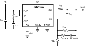
This section provides several application solutions with an associated bill of materials, listed in Table 5 to Table 7. All bill of materials reference the schematic in Figure 44. The compensation for each solution was optimized to work over the full input range. Many applications have a fixed input voltage rail. It is possible to modify the compensation to obtain a faster transient response for a given input voltage operating point.
 Figure 44. LM2854 Application Circuit Schematic
Table 5. LM2854 500-kHz Bill of Materials, VIN = 5 V, VOUT = 3.3 V, IOUT(MAX) = 4 A, Optimized for Efficiency
| REF DES | DESCRIPTION | CASE SIZE | MANUFACTURER | MANUFACTURER P/N |
|---|---|---|---|---|
| U1 | Synchronous Buck Regulator | HTSSOP-16 | Texas Instruments | LM2854MHX-500 |
| CIN | 47 µF, X5R, 10 V | 1210 | TDK | C3225X5R1A476M |
| CO | 100 µF, X5R, 6.3 V | 1210 | TDK | C3225X5R0J107M |
| LO | 1.5 µH, 9.7 mΩ, 10 A | 7.1 × 6.5 × 3.0 mm | TDK | SPM6530T-1R5M100 |
| RFB1 | 249 kΩ | 0603 | Vishay Dale | CRCW06032493F-e3 |
| RFB2 | 80.6 kΩ | 0603 | Vishay Dale | CRCW060328062F-e3 |
| RCOMP | 1 kΩ | 0603 | Vishay Dale | CRCW06031001F-e3 |
| RF | 1 Ω | 0603 | Vishay Dale | CRCW06031R0F-e3 |
| CCOMP | 33 pF, ±5%, C0G, 50 V | 0603 | TDK | C1608C0G1H330J |
| CSS | 10 nF, ±10%, X7R, 16 V | 0603 | Murata | GRM188R71C103KA01 |
| CF | 1.0 µF, ±10%, X7R, 10 V | 0603 | Murata | GRM188R71A105KA61 |
Table 6. LM2854 1-MHz Bill of Materials, VIN = 3.3 V to 5 V, VOUT = 2.5 V, IOUT (MAX) = 4 A, Optimized for Electrolytic Input and Output Capacitance
| REF DES | DESCRIPTION | CASE SIZE | MANUFACTURER | MANUFACTURER P/N |
|---|---|---|---|---|
| U1 | Synchronous Buck Regulator | HTSSOP-16 | Texas Instruments | LM2854MHX-1000 |
| CIN | 150 µF, 6.3 V, 18 mΩ | C2, 6 × 3.2 × 1.8 mm | Sanyo | 6TPE150MIC2 |
| CO | 330 µF, 6.3 V, 18 mΩ | D3L, 7.3 × 4.3 × 2.8 mm | Sanyo | 6TPE330MIL |
| LO | 2.2 µH, 16 mΩ, 7 A | 6.47 × 6.86 × 3 mm | Vishay Dale | IHLP2525CZER2R2M11 |
| RFB1 | 100 kΩ | 0603 | Vishay Dale | CRCW06031003F-e3 |
| RFB2 | 47.5 kΩ | 0603 | Vishay Dale | CRCW060324752F-e3 |
| RCOMP | 15 kΩ | 0603 | Vishay Dale | CRCW06031502F-e3 |
| RF | 1 Ω | 0603 | Vishay Dale | CRCW06031R0F-e3 |
| CCOMP | 330 pF, ±5%, C0G, 50 V | 0603 | TDK | C1608C0G1H331J |
| CSS | 10 nF, ±10%, X7R, 16 V | 0603 | Murata | GRM188R71C103KA01 |
| CF | 1 µF,±10%, X7R, 10 V | 0603 | Murata | GRM188R71A105KA61 |
Table 7. LM2854 1-MHz Bill of Materials, VIN = 3.3 V, VOUT = 0.8 V, IOUT (MAX) = 4 A, Optimized for Solution Size and Transient Response
| REF DES | DESCRIPTION | CASE SIZE | MANUFACTURER | MANUFACTURER P/N |
|---|---|---|---|---|
| U1 | Synchronous Buck Regulator | HTSSOP-16 | Texas Instruments | LM2854MHX-1000 |
| CIN | 47 µF, X5R, 6.3 V | 1206 | TDK | C3216X5R0J476M |
| CO | 47 µF, X5R, 6.3 V | 1206 | TDK | C3216X5R0J476M |
| LO | 0.47 µH, 14.5 mΩ, 7 A | 4.06 × 4.45 × 2.00 mm | Vishay Dale | IHLP1616BZER0R47M11 |
| RFB1 | 110 kΩ | 0402 | Vishay Dale | CRCW04021103F-e3 |
| RCOMP | 1 kΩ | 0402 | Vishay Dale | CRCW04021001F-e3 |
| RF | 1 Ω | 0402 | Vishay Dale | CRCW04021R0F-e3 |
| CCOMP | 27 pF, ±5%, C0G, 50 V | 0402 | Murata | GRM1555C1H270JZ01 |
| CSS | 10 nF, ±10%, X7R, 16 V | 0402 | Murata | GRM155R71C103KA01 |
| CF | 1 µF, ±10%, X7R, 10 V | 0402 | Murata | GRM155R61A105KE15 |