JAJSAH6H January 2006 – October 2017 LM3100
PRODUCTION DATA.
- 1 特長
- 2 アプリケーション
- 3 概要
- 4 改訂履歴
- 5 Pin Configuration and Functions
- 6 Specifications
- 7 Detailed Description
- 8 Applications and Implementation
- 9 Layout
- 10デバイスおよびドキュメントのサポート
- 11メカニカル、パッケージ、および注文情報
パッケージ・オプション
メカニカル・データ(パッケージ|ピン)
- PWP|20
サーマルパッド・メカニカル・データ
- PWP|20
発注情報
6.6 Typical Characteristics
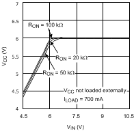
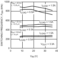
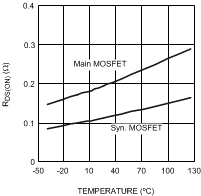
All curves taken at VIN = 18 V with configuration in typical application circuit for VOUT = 3.3 V shown in this datasheet. TA = 25°C, unless otherwise specified.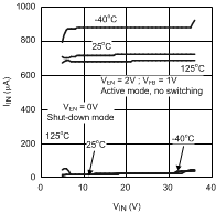
1.
Figure 1. Quiescent Current, IIN vs VIN
1.
Figure 3. VCC vs VIN
1.
Figure 5. Switching Frequency, FSW vs VIN
1.
Figure 7. RDS(ON) vs Temperature
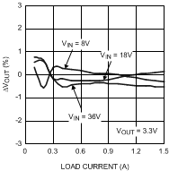
1.
Figure 9. VOUT Regulation vs Load Current
| VOUT = 3.3 V |
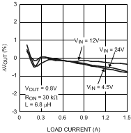
1.
Figure 11. VOUT Regulation vs Load Current
| VOUT = 0.8 V |
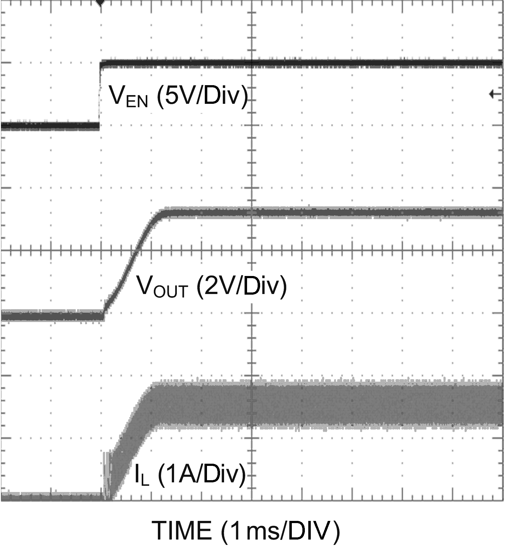
1.
Figure 13. Enable Transient
| VOUT = 3.3 V, 1.5 A Loaded |
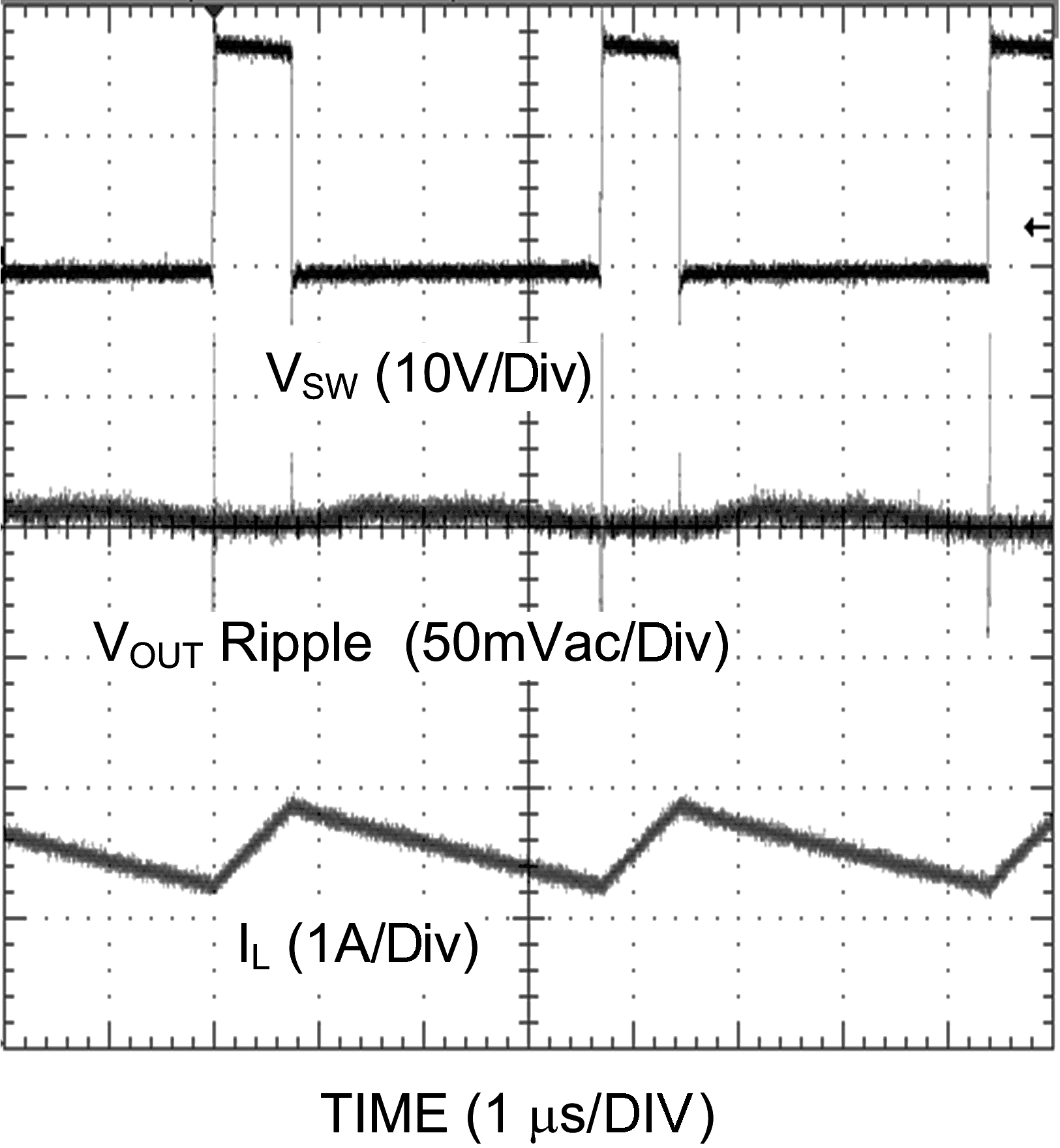
1.
Figure 15. Continuous Mode Operation
| VOUT = 3.3 V, 1.5 A Loaded |
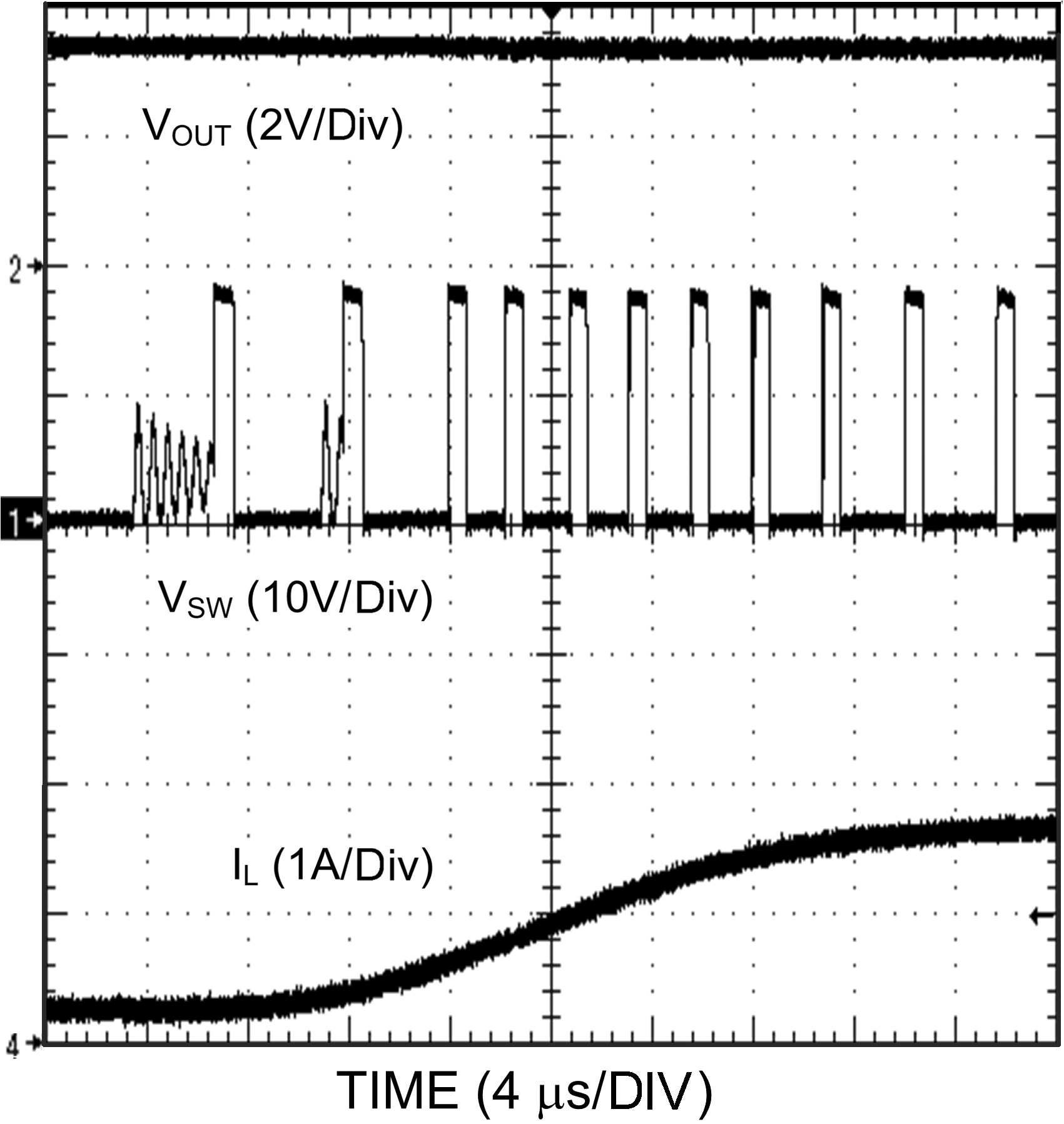
1.
Figure 17. CCM to DCM Transition
| VOUT = 3.3 V, 0.15 A - 1.5 A Load |
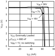
1.
Figure 2. VCC vs ICC
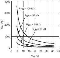
1.
Figure 4. TON vs VIN
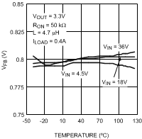
1.
Figure 6. VFB vs Temperature
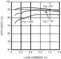
1.
Figure 8. Efficiency vs Load Current
| VOUT = 3.3 V | ||
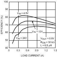
1.
Figure 10. Efficiency vs Load Current
| VOUT = 0.8 V |
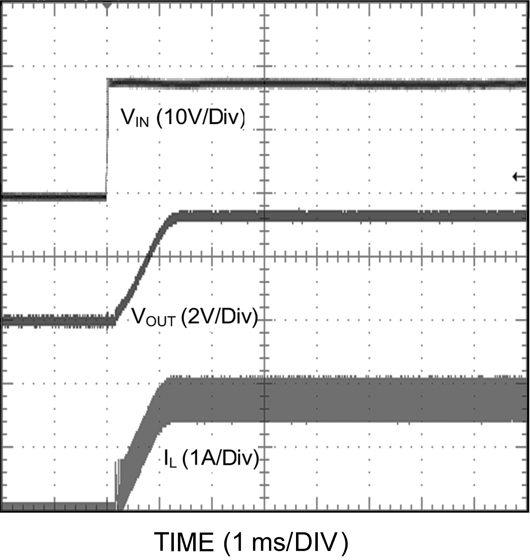
1.
Figure 12. Power Up
| VOUT = 3.3 V, 1.5 A Loaded | ||
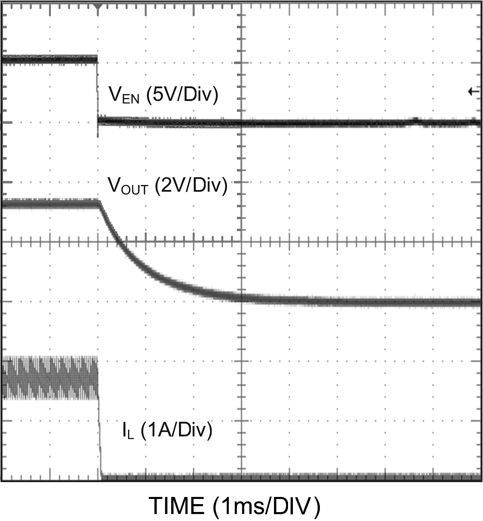
1.
Figure 14. Shutdown Transient
| VOUT = 3.3 V, 1.5 A Loaded |
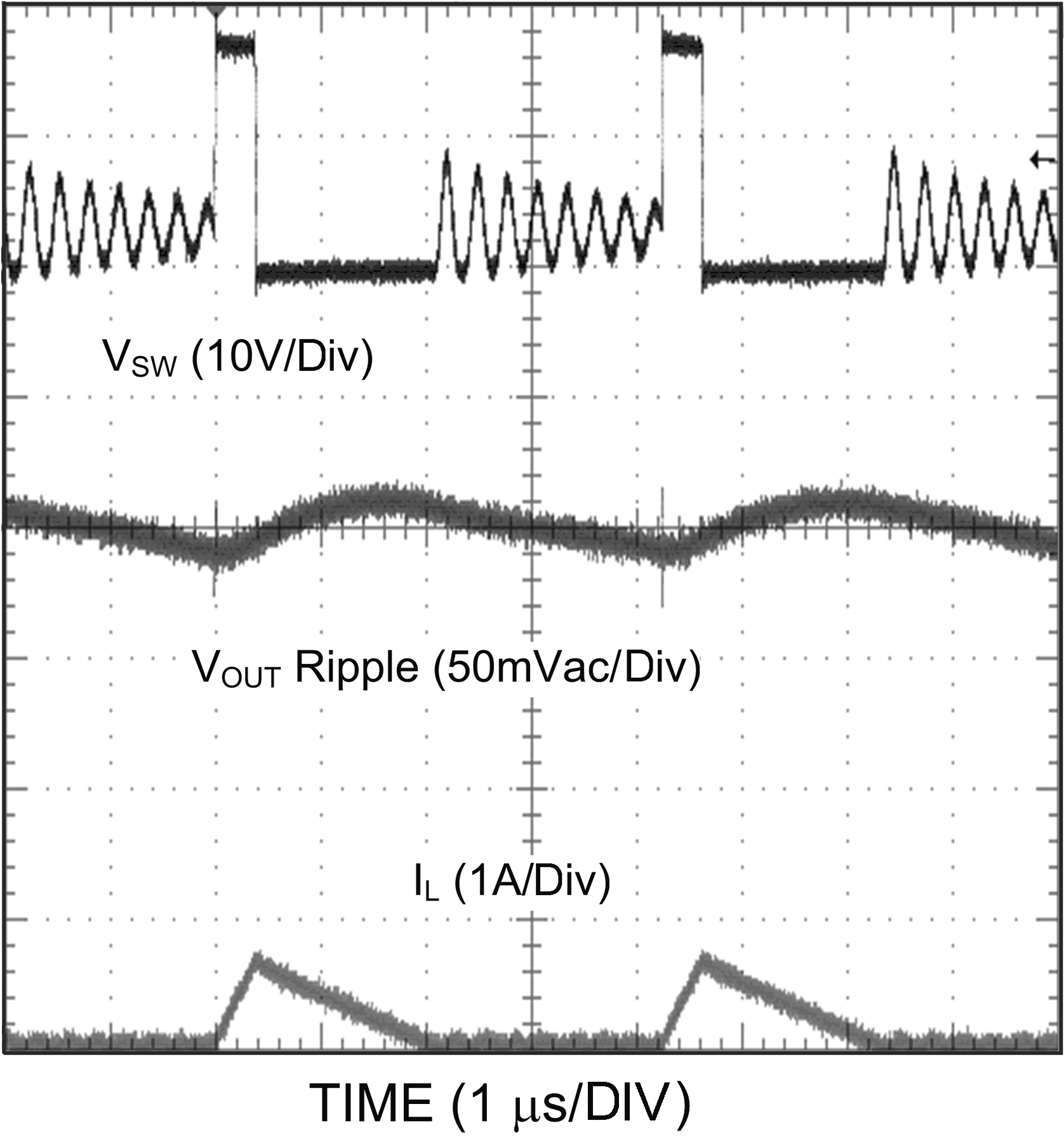
1.
Figure 16. Discontinuous Mode Operation
| VOUT = 3.3 V, 0.15 A Loaded |
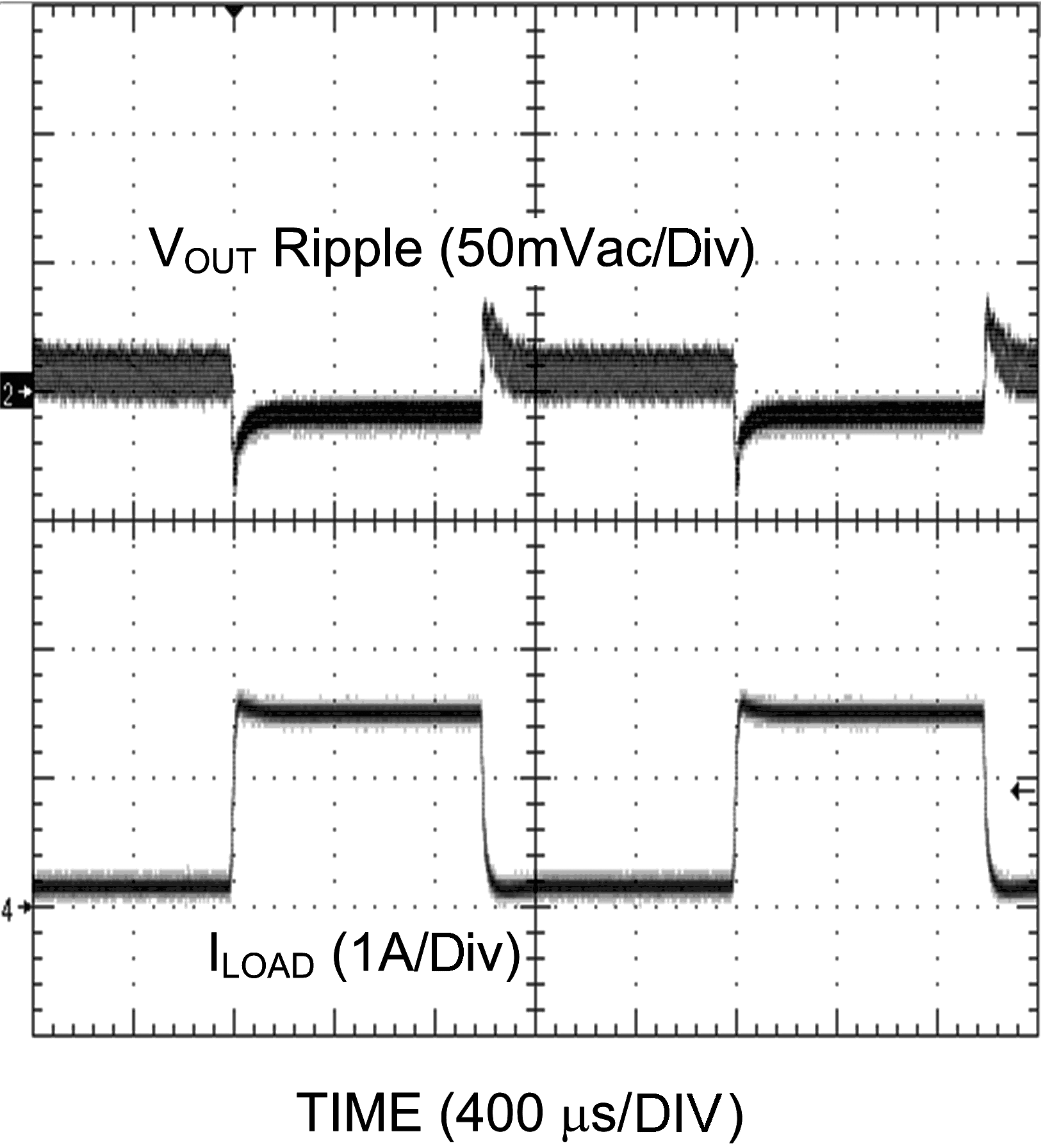
1.
Figure 18. Load Transient
| VOUT = 3.3 V, 0.15 A - 1.5 A Load | Current slew-rate: 2.5 A/µs | |