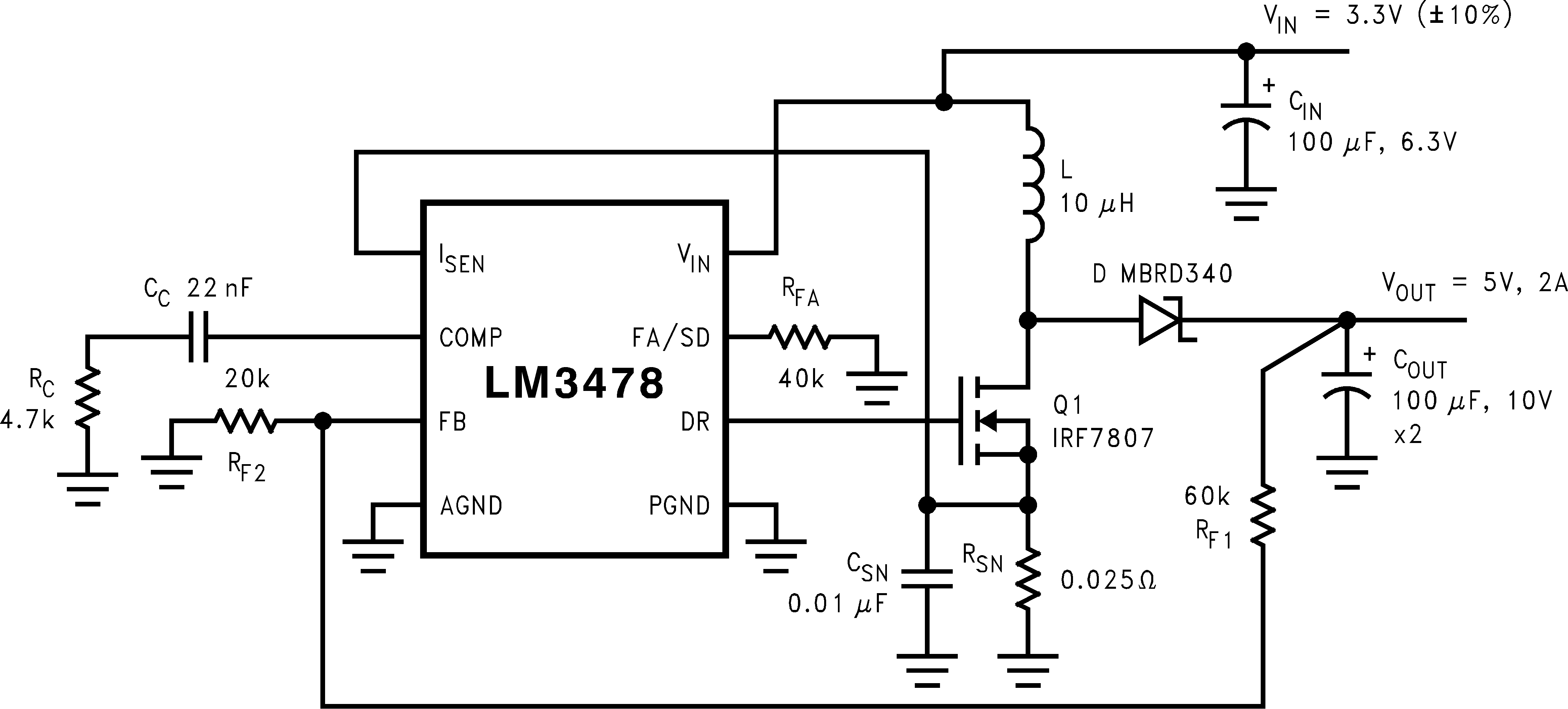
LM3478は、スイッチング・レギュレータ用の多用途ローサイドNチャネルMOFFETコントローラです。昇圧、フライバック、SEPICなど、ローサイドMOSFETを必要とするトポロジでの使用に適しています。さらに、LM3478は非常に高いスイッチング周波数で動作可能なため、ソリューション全体を小型化できます。LM3478のスイッチング周波数は、単一の外付け抵抗を使用して、100kHz~1MHzの任意の値に設定できます。電流モード制御により、帯域幅と過渡応答が優れており、サイクル単位の電流制限機能もあります。出力電流は、単一の外付け抵抗によりプログラム可能です。
LM3478にはサーマル・シャットダウン、短絡保護、過電圧保護などの機能が組み込まれています。省電力シャットダウン・モードにより、合計消費電流が5μAに低減され、電源シーケンシングを実行できます。内部的なソフトスタートにより、スタートアップ時の突入電流が制限されます。
型番 | パッケージ | 本体サイズ(公称) |
---|---|---|
LM3478 | SOIC (8) | 4.90mm×3.91mm |
VSSOP (8) | 3.00mm×3.00mm |
Changes from W Revision (December 2014) to X Revision
Changes from V Revision (February 2013) to W Revision
Changes from U Revision (February 2013) to V Revision
PIN | I/O | DESCRIPTION | |
---|---|---|---|
NAME | NO. | ||
ISEN | 1 | I | Current sense input pin. Voltage generated across an external sense resistor is fed into this pin. |
COMP | 2 | I | Compensation pin. A resistor, capacitor combination connected to this pin provides compensation for the control loop. |
FB | 3 | I | Feedback pin. The output voltage should be adjusted using a resistor divider to provide 1.26 V at this pin. |
AGND | 4 | G | Analog ground pin. |
PGND | 5 | G | Power ground pin. |
DR | 6 | O | Drive pin. The gate of the external MOSFET should be connected to this pin. |
FA/SD | 7 | I | Frequency adjust and Shutdown pin. A resistor connected to this pin sets the oscillator frequency. A high level on this pin for longer than 30 µs will turn the device off. The device will then draw less than 10µA from the supply. |
VIN | 8 | P | Power Supply Input pin. |
MIN | MAX | UNIT | ||
---|---|---|---|---|
Input Voltage | 45 | V | ||
FB Pin Voltage | –0.4< V | V FB < 7 | V | |
FA/SD Pin Voltage | –0.4 < VFA/SD | VFA/SD< 7 | V | |
Peak Driver Output Current (<10µs) | 1 | A | ||
Power Dissipation | Internally Limited | |||
Junction Temperature | +150 | °C | ||
Lead Temperature | Vapor Phase (60 s) | 215 | °C | |
Infrared (15 s) | 260 | °C | ||
DR Pin Voltage | –0.4 ≤ VDR | VDR ≤ 8 | V | |
ISEN Pin Voltage | 500 | mV | ||
Tstg | Storage temperature | −65 | 150 | °C |
VALUE | UNIT | ||||
---|---|---|---|---|---|
V(ESD) | Electrostatic discharge | Human body model (HBM), per ANSI/ESDA/JEDEC JS-001, all pins(1) | ±2000 | V | |
Charged device model (CDM), per JEDEC specification JESD22-C101, all pins(2) | ±750 |
MIN | NOM | MAX | UNIT | ||
---|---|---|---|---|---|
Supply Voltage | 2.97 ≤ VIN | VIN ≤ 40 | V | ||
Junction Temperature Range | −40 ≤ TJ | TJ ≤ +125 | °C | ||
Switching Frequency | 100 ≤ FSW | FSW ≤ 1 | MHz |
THERMAL METRIC(1) | LM3478 | UNIT | ||
---|---|---|---|---|
D | DGK | |||
8 PINS | 8 PINS | |||
RθJA | Junction-to-ambient thermal resistance | 105.3 | 157.2 | °C/W |
RθJC(top) | Junction-to-case (top) thermal resistance | 50.3 | 49.9 | °C/W |
RθJB | Junction-to-board thermal resistance | 55.8 | 77.1 | °C/W |
ψJT | Junction-to-top characterization parameter | 6.8 | 4.7 | °C/W |
ψJB | Junction-to-board characterization parameter | 54.7 | 75.8 | °C/W |
RθJC(bot) | Junction-to-case (bottom) thermal resistance | N/A | N/A | °C/W |
PARAMETER | TEST CONDITIONS | MIN | TYP | MAX | UNIT | |
---|---|---|---|---|---|---|
VFB | Feedback Voltage | VCOMP = 1.4V, 2.97 ≤ VIN ≤ 40V | 1.2416 | 1.26 | 1.2843 | V |
VCOMP = 1.4V, 2.97 ≤ VIN ≤ 40V, −40°C ≤ TJ ≤ 125°C | 1.228 | 1.292 | ||||
ΔVLINE | Feedback Voltage Line Regulation | 2.97 ≤ VIN ≤ 40V | 0.001 | %/V | ||
ΔVLOAD | Output Voltage Load Regulation | IEAO Source/Sink | ±0.5 | %/A | ||
VUVLO | Input Undervoltage Lock-out | 2.85 | V | |||
−40°C ≤ TJ ≤ 125°C | 2.97 | |||||
VUV(HYS) | Input Undervoltage Lock-out Hysteresis | 170 | mV | |||
−40°C ≤ TJ ≤ 125°C | 130 | 210 | ||||
Fnom | Nominal Switching Frequency | RFA = 40KΩ | 400 | kHz | ||
RFA = 40KΩ, −40°C ≤ TJ ≤ 125°C | 350 | 440 | ||||
RDS1 (ON) | Driver Switch On Resistance (top) | IDR = 0.2A, VIN= 5V | 16 | Ω | ||
RDS2 (ON) | Driver Switch On Resistance (bottom) | IDR = 0.2A | 4.5 | |||
VDR (max) | Maximum Drive Voltage Swing(2) | VIN < 7.2V | VIN | V | ||
VIN ≥ 7.2V | 7.2 | |||||
Dmax | Maximum Duty Cycle(3) | 100% | ||||
Tmin (on) | Minimum On Time | 325 | ns | |||
−40°C ≤ TJ ≤ 125°C | 210 | 600 | ||||
ISUPPLY | Supply Current (non-switching) | See (5) | 2.7 | mA | ||
See (5), −40°C ≤ TJ ≤ 125°C | 3.3 | |||||
IQ | Quiescent Current in Shutdown Mode | VFA/SD = 5V (6), VIN = 5V | 5 | µA | ||
VFA/SD = 5V (6), VIN = 5V, −40°C ≤ TJ ≤ 125°C | 10 | |||||
VSENSE | Current Sense Threshold Voltage | VIN = 5V | 135 | 156 | 180 | mV |
VIN = 5V, −40°C ≤ TJ ≤ 125°C | 125 | 190 | ||||
VSC | Short-Circuit Current Limit Sense Voltage | VIN = 5V | 343 | mV | ||
VIN = 5V, −40°C ≤ TJ ≤ 125°C | 250 | 415 | ||||
VSL | Internal Compensation Ramp Voltage | VIN = 5V | 92 | mV | ||
VIN = 5V, −40°C ≤ TJ ≤ 125°C | 52 | 132 | ||||
VSL ratio | VSL/VSENSE | 0.30 | 0.49 | 0.70 | ||
VOVP | Output Over-voltage Protection (with respect to feedback voltage) (4) | VCOMP = 1.4V | 32 | 50 | mV | |
VCOMP = 1.4V, −40°C ≤ TJ ≤ 125°C | 25 | |||||
VSSOP Package | 78 | |||||
VSSOP Package, −40°C ≤ TJ ≤ 125°C | 85 | |||||
SOIC Package | 78 | |||||
SOIC Package, −40°C ≤ TJ ≤ 125°C | 100 | |||||
VOVP(HYS) | Output Over-Voltage Protection Hysteresis(4) | VCOMP = 1.4V | 60 | mV | ||
VCOMP = 1.4V, −40°C ≤ TJ ≤ 125°C | 20 | 110 | ||||
Gm | Error Amplifier Transconductance | VCOMP = 1.4V, IEAO = 100µA (Source/Sink) | 600 | 800 | 1000 | µS |
VCOMP = 1.4V, IEAO = 100µA (Source/Sink), −40°C ≤ TJ ≤ 125°C | 365 | 1265 | ||||
AVOL | Error Amplifier Voltage Gain | VCOMP = 1.4V, IEAO = 100µA (Source/Sink) | 38 | V/V | ||
VCOMP = 1.4V, IEAO = 100µA (Source/Sink), −40°C ≤ TJ ≤ 125°C | 26 | 44 | ||||
IEAO | Error Amplifier Output Current (Source/ Sink) | Source, VCOMP = 1.4V, VFB = 0V | 80 | 110 | 140 | µA |
Source, VCOMP = 1.4V, VFB = 0V, −40°C ≤ TJ ≤ 125°C | 50 | 180 | ||||
Sink, VCOMP = 1.4V, VFB = 1.4V | −100 | −140 | −180 | µA | ||
Sink, VCOMP = 1.4V, VFB = 1.4V, −40°C ≤ TJ ≤ 125°C | −85 | −185 | ||||
VEAO | Error Amplifier Output Voltage Swing | Upper Limit, VFB = 0V, COMP Pin = Floating | 2.2 | V | ||
Upper Limit, VFB = 0V, COMP Pin = Floating, −40°C ≤ TJ ≤ 125°C | 1.8 | 2.4 | ||||
Lower Limit, VFB = 1.4V | 0.56 | V | ||||
Lower Limit, VFB = 1.4V, −40°C ≤ TJ ≤ 125°C | 0.2 | 1.0 | ||||
TSS | Internal Soft-Start Delay | VFB = 1.2V, VCOMP = Floating | 4 | ms | ||
Tr | Drive Pin Rise Time | Cgs = 3000pf, VDR = 0 to 3V | 25 | ns | ||
Tf | Drive Pin Fall Time | Cgs = 3000pf, VDR = 0 to 3V | 25 | ns | ||
VSD | Shutdown threshold (1) | Output = High | 1.27 | V | ||
Output = High, −40°C ≤ TJ ≤ 125°C | 1.4 | |||||
Output = Low | 0.65 | V | ||||
Output = Low, −40°C ≤ TJ ≤ 125°C | 0.3 | |||||
ISD | Shutdown Pin Current | VSD = 5V | −1 | µA | ||
VSD = 0V | +1 | |||||
IFB | Feedback Pin Current | 15 | nA | |||
TSD | Thermal Shutdown | 165 | °C | |||
Tsh | Thermal Shutdown Hysteresis | 10 | °C |