JAJSEX5B August 2010 – March 2018 LM3535
PRODUCTION DATA.
- 1 特長
- 2 アプリケーション
- 3 概要
- 4 改訂履歴
- 5 概要(続き)
- 6 Pin Configuration and Functions
- 7 Specifications
- 8 Detailed Description
-
9 Application and Implementation
- 9.1 Application Information
- 9.2
Typical Application
- 9.2.1 Design Requirements
- 9.2.2 Detailed Design Procedure
- 9.2.3 Application Curves
- 10Power Supply Recommendations
- 11Layout
- 12デバイスおよびドキュメントのサポート
- 13メカニカル、パッケージ、および注文情報
9.2.2.1.3 ALS Averaging Time
The ALS averaging time is the time over which the averager block collects samples from the A/D converter and then averages them to pass to the discriminator block (see Figure 32). Ambient light sensor samples are averaged and then further processed by the discriminator block to provide rejection of noise and transient signals. The averager is configurable with 8 different averaging times to provide varying amounts of noise and transient rejection (see Figure 25). The discriminator block algorithm has a maximum latency of two averaging cycles, therefore the averaging time selection determines the amount of delay that will exist between a steady state change in the ambient light conditions and the associated change of the backlight illumination. For example, the A/D converter samples the ALS inputs at 16 kHz. If the averaging time is set to 800 ms, the averager sends the updated zone information to the discriminator every 800 ms. This zone information contains the average of approximately 12800 samples (800 ms × 16 kHz). Due to the latency of 2 averaging cycles, when there is a steady-state change in the ambient light, the LED current begins to transition to the appropriate target value after approximately 1600 ms have elapsed.
The sign and magnitude of these averager outputs are used to determine whether the LM3535 should change brightness zones. The averager block follows the following rules to make a zone transition:
- The averager always begins with a Zone0 reading stored at start-up. If the main display LEDs are active before the ALS block is enabled, it is recommended that the ALS-EN bit be enabled at least 3 averaging cycles times before the ALS-ENA bit is enabled.
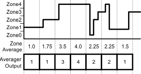
- The averager always rounds down to the lower zone in the case of a non-integer zone average (1.2 rounds to 1 and 1.75 also rounds to 1). Figure 32 shows an example of how the Averager will make the zone decisions for different ambient conditions.
 Figure 32. Averager Calculation
 - The two most current averaging samples are used to make zone change decisions.
- To make a zone change, data from three averaging cycles are needed (starting value, first transition, second transition or rest).
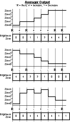
- To Increase the brightness zone, a positive averager zone output must be followed by a second positive averager output or a repeated Averager zone. ('+' to '+' or '+' to 'Rest')
- To decrease the brightness zone, a negative averager zone output must be followed by a second negative averager output or a repeated Averager zone. ('-' to '-' or '-' to 'Rest')
- In the case of two increases or decreases in the averager output, the LM3535 transitions to zone equal to the last averager output.
Figure 33 provides a graphical representation of the behavior of the averager.
 Figure 33. Brightness Zone Change Examples
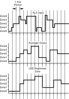
 Using the diagram for the ALS block (Figure 30), Figure 34 shows the flow of information starting with the A/D, transitioning to the averager, followed by the discriminator. Each state filters the previous output to help prevent unwanted zone to zone transitions.
 Figure 34. Ambient Light Input To Backlight Mapping
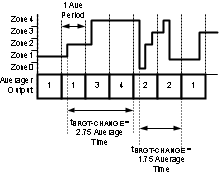
 When using the ALS averaging functionality, it is important to remember that the averaging cycle is free running and is not synchronized with changing ambient lighting conditions. Due to the nature of the averager round down, an increase in brightness can take between 2 and 3 averaging cycles to change zones while a decrease in brightness can take between 1 and 2 averaging cycles to change. See Figure 25 for a list of possible averager periods. Figure 35 shows an example of how the perceived brightness change time can vary.
 Figure 35. Perceived Brightness Change Time