SNVS594G December 2008 – April 2016 LM3555
PRODUCTION DATA.
- 1 Features
- 2 Applications
- 3 Description
- 4 Revision History
- 5 Pin Configuration and Functions
- 6 Specifications
-
7 Detailed Description
- 7.1 Overview
- 7.2 Functional Block Diagram
- 7.3 Feature Description
- 7.4 Device Functional Modes
- 7.5 Programming
- 7.6 Register Maps
- 8 Application and Implementation
- 9 Power Supply Recommendations
- 10Layout
- 11Device and Documentation Support
- 12Mechanical, Packaging, and Orderable Information
10 Layout
10.1 Layout Guidelines
The DSBGA is a chip-scale package with good thermal properties. For more detailed instructions on handling and mounting DSBGA packages, refer to AN-1112 DSBGA Wafer Level Chip Scale Package (SNVA009).
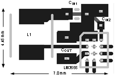
The high switching frequencies and large peak currents make the PCB layout a critical part of the design. The proceeding steps must be followed to ensure stable operation and proper current source regulation.
- Connect the inductor as close to the SW pin as possible. This reduces the inductance and resistance of the switching node which minimizes ringing and excess voltage drops.
- Connect the return terminals of the input capacitor and the output capacitor as close to the two ground pins (PGND and SGND) as possible and through low impedance traces.
- Bypass VIN with a 10-µF ceramic capacitor and an additional 0.1-µF ceramic capacitor. Connect the positive terminal of this capacitor as close to VIN as possible.
- Connect COUT as close to the VOUT pin as possible. This reduces the inductance and resistance of the output bypass node which minimizes ringing and voltage drops. This improves efficiency and decreases the noise injected into the current sources.
10.2 Layout Example
 Figure 58. LM3555 Layout