JAJSH28D
November 2013 – March 2019
LM3697
PRODUCTION DATA.
1
特長
2
アプリケーション
3
概要
Device Images
概略回路図
昇圧効率
4
改訂履歴
5
Pin Configuration and Functions
Pin Functions
6
Specifications
6.1
Absolute Maximum Ratings
6.2
ESD Ratings
6.3
Recommended Operating Conditions
6.4
Thermal Information
6.5
Electrical Characteristics
6.6
Timing Requirements
6.7
Typical Characteristics
7
Detailed Description
7.1
Overview
7.1.1
PWM Input
7.1.2
HWEN Input
7.1.3
Thermal Shutdown
7.2
Functional Block Diagram
7.3
Feature Descriptions
7.3.1
High-Voltage LED Control
7.3.1.1
High-Voltage Boost Converter
7.3.1.2
High-Voltage Current Sinks (HVLED1, HVLED2 and HVLED3)
7.3.1.3
High-Voltage Current String Biasing
7.3.2
Boost Switching-Frequency Select
7.3.3
Automatic Switching Frequency Shift
7.3.4
Brightness Register Current Control
7.3.4.1
8-Bit Control (Preferred)
7.3.4.2
11-Bit Control
7.3.5
PWM Control
7.3.5.1
PWM Input Frequency Range
7.3.5.2
PWM Input Polarity
7.3.5.3
PWM Zero Detection
7.3.6
Start-up/Shutdown Ramp
7.3.7
Run-Time Ramp
7.3.8
High-Voltage Control A and B Ramp Select
7.4
Device Functional Modes
7.4.1
LED Current Mapping Modes
7.4.1.1
Exponential Mapping
7.4.1.1.1
8-Bit Code Calculation
7.4.1.1.2
11-Bit Code Calculation
7.4.1.2
Linear Mapping
7.4.1.2.1
8-Bit Code Calculation
7.4.1.2.2
11-Bit Code Calculation
7.4.2
Fault Flags/Protection Features
7.4.2.1
Open LED String (HVLED)
7.4.2.2
Shorted LED String (HVLED)
7.4.2.3
Overvoltage Protection (Inductive Boost)
7.4.2.4
Current Limit (Inductive Boost)
7.4.3
I2C-Compatible Interface
7.4.3.1
Start And Stop Conditions
7.4.3.2
I2C-Compatible Address
7.4.3.3
Transferring Data
7.4.3.4
High-Speed Mode
7.5
Register Maps
8
Application and Implementation
8.1
Application Information
8.2
Typical Applications
8.2.1
Design Requirements
8.2.2
Detailed Design Procedure
8.2.2.1
Boost Converter Maximum Output Power
8.2.2.1.1
Peak Current Limited
8.2.2.1.2
Output Voltage Limited
8.2.2.2
Inductor Selection
8.2.2.3
Output Capacitor Selection
8.2.2.4
Schottky Diode Selection
8.2.2.5
Input Capacitor Selection
8.2.2.6
Application Circuit Component List
8.2.3
Application Performance Plots
8.3
Initialization Set Up
9
Power Supply Recommendations
10
Layout
10.1
Layout Guidelines
10.1.1
Boost Output Capacitor Placement
10.1.2
Schottky Diode Placement
10.1.3
Inductor Placement
10.1.4
Boost Input Capacitor Placement
10.2
Layout Example
11
デバイスおよびドキュメントのサポート
11.1
デバイス・サポート
11.1.1
デベロッパー・ネットワークの製品に関する免責事項
11.2
関連資料
11.3
ドキュメントの更新通知を受け取る方法
11.4
コミュニティ・リソース
11.5
商標
11.6
静電気放電に関する注意事項
11.7
Glossary
12
メカニカル、パッケージ、および注文情報
パッケージ・オプション
デバイスごとのパッケージ図は、PDF版データシートをご参照ください。
メカニカル・データ(パッケージ|ピン)
YFQ|12
サーマルパッド・メカニカル・データ
発注情報
jajsh28d_oa
jajsh28d_pm
6.7
Typical Characteristics
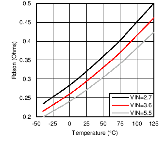
Figure 2.
R
DSON
vs Temperature
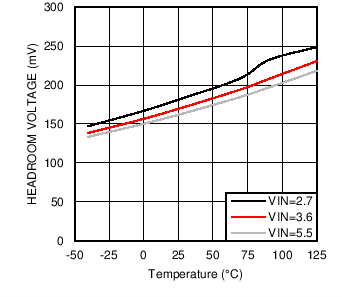
Figure 4.
V
HR_MIN
vs Temperature
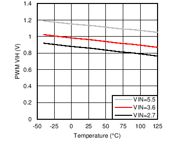
Figure 6.
PWM V
IH
vs Temperature
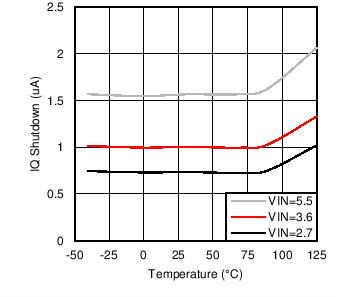
Figure 3.
I
Q
Shutdown vs Temperature
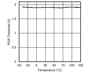
Figure 5.
POR Threshold vs Temperature
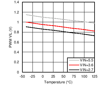
Figure 7.
PWM V
IL
vs Temperature