SNVS088F May 2004 – April 2016 LM3704
PRODUCTION DATA.
7 Application and Implementation
NOTE
Information in the following applications sections is not part of the TI component specification, and TI does not warrant its accuracy or completeness. TI’s customers are responsible for determining suitability of components for their purposes. Customers should validate and test their design implementation to confirm system functionality.
7.1 Application Information
The LM3704 is a microprocessor supervisory circuit that provides the maximum flexibility for monitoring power supplies and battery-controlled functions. The reset threshold is typically 3.08 V but can be customized for voltages between 2.2 V and 5 V in 10-mV increments by contacting Texas Instruments. The power-fail input, which is a 1.225-V threshold detector for power-fail warning, can be adjusted using a resistor divider as shown in Figure 11. This section shows various application circuits to provide different monitoring solutions.
7.2 Typical Application
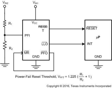 Figure 11. Monitoring Two Critical Supplies
7.2.1 Design Requirements
The component count is minimal; employing two resistors as part of a voltage-divider circuit is all that is needed for the typical application of monitoring two critical supplies shown in Figure 11.
7.2.2 Detailed Design Procedure
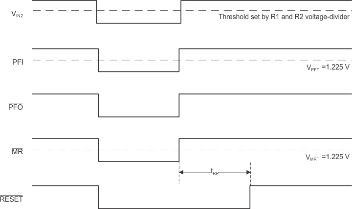
The voltage-divider circuit that connects to the power-fail reset pin is chosen such that the reset threshold at the device is 1.225 V as shown in Figure 11.
7.2.3 Application Curves

7.3 System Examples
The LM3704 voltage supervisor has various features such as power-fail input detection, low-line output, and manual reset while requiring few to no additional components making it versatile and easy-to-use. See Figure 14 through Figure 18 for a variety of circuit applications.
spacer
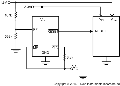 Figure 14. Monitoring Two Supplies Plus Manual Reset
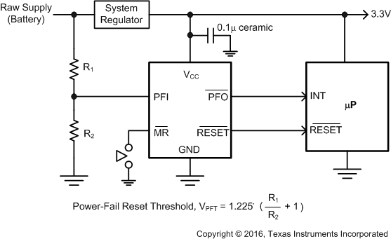
With Early Warning Detector
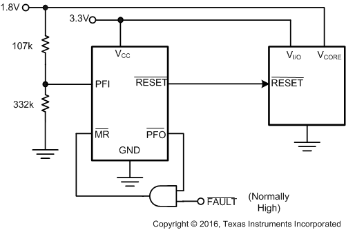 Figure 15. Monitoring Dual Supplies
Plus External Fault Input
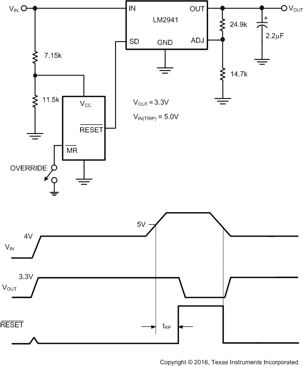 Figure 17. Regulator/Switch With Long-Term Overvoltage Lockout
Prevents Overdissipation in Linear Regulator
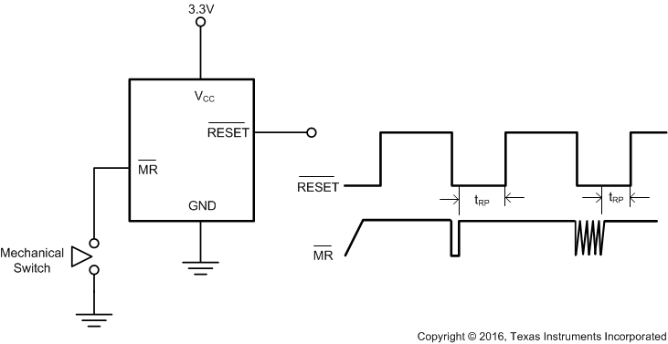 Figure 18. Switch Debouncer