-
LM5067 負電圧ホット・スワップ / 突入電流コントローラ、電力制限付
- 1 特長
- 2 アプリケーション
- 3 概要
- 4 Revision History
- 5 Device Comparison
- 6 Pin Configuration and Functions
- 7 Specifications
- 8 Detailed Description
-
9 Application and Implementation
- 9.1 Application Information
- 9.2
Typical Application
- 9.2.1 Design Requirements
- 9.2.2 Detailed Design Procedure
- 9.2.3 Application Curves
- 10Power Supply Recommendations
- 11Layout
- 12Device and Documentation Support
- 13Mechanical, Packaging, and Orderable Information
- 重要なお知らせ
パッケージ・オプション
メカニカル・データ(パッケージ|ピン)
サーマルパッド・メカニカル・データ
発注情報
DATA SHEET
LM5067 負電圧ホット・スワップ / 突入電流コントローラ、電力制限付
このリソースの元の言語は英語です。 翻訳は概要を便宜的に提供するもので、自動化ツール (機械翻訳) を使用していることがあり、TI では翻訳の正確性および妥当性につきましては一切保証いたしません。 実際の設計などの前には、ti.com で必ず最新の英語版をご参照くださいますようお願いいたします。
1 特長
- 幅広い動作範囲:-9V~-80V
- 突入電流制限機能により、動作中の電源に基板を安全に挿入可能
- 外部パス・デバイスの最大消費電力をプログラム可能
- 調整可能な電流制限
- 深刻な過電流時のサーキット・ブレーカ機能
- 可変の低電圧誤動作防止 (UVLO) とヒステリシス
- 可変の過電圧誤動作防止 (OVLO) とヒステリシス
- 初期挿入タイマにより、システム接続後のリンギングや過渡現象を沈静化可能
- プログラム可能なフォルト・タイマにより不要な保護動作を回避
- アクティブ HIGH のオープン・ドレイン POWER GOOD 出力
- ラッチ付きフォルト・バージョンと自動再起動バージョンを提供
2 アプリケーション
- サーバーのバックプレーン・システム
- 突入電流の制限
- ソリッド・ステート・サーキット・ブレーカ
- 過渡電圧保護
- ソリッド・ステート・リレー
- 低電圧誤動作防止
- パワー・グッド検出器とインジケータ
3 概要
LM5067 負電圧ホット・スワップ・コントローラは、稼働中のシステム・バックプレーンまたはその他の通電中の電源に回路基板を挿抜する際、電源接続をインテリジェントに制御できます。LM5067 は、突入電流制御によってシステムの電圧ドループや過渡現象を制限します。外部の直列パス N チャネル MOSFET での電流制限と消費電力はプログラム可能であり、安全動作領域 (SOA) 内での動作が保証されます。さらに、 LM5067 は、過電流および過電圧状態を監視することで回路を保護します。POWER GOOD 出力は、出力電圧が入力電圧に近い値であることを示します。入力の低電圧 / 過電圧誤動作防止のレベルとヒステリシス、および障害検出時間は、プログラム可能です。LM5067-1 は、障害検出後はオフにラッチされます。LM5067-2 は、固定されたデューティ・サイクルで自動的に再起動を試みます。LM5067 は10 ピンの VSSOP パッケージおよび 14 ピンの SOIC パッケージで供給されます。
製品情報(1)
| 部品番号 | パッケージ | 本体サイズ (公称) |
|---|---|---|
| LM5067 | VSSOP (10) | 3.00mm × 3.00mm |
| SOIC (14) | 8.99mm × 7.49mm |
(1) 利用可能なすべてのパッケージについては、このデータシートの末尾にある注文情報を参照してください。
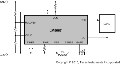
 負電源バスの突入電流と障害保護
4 Revision History
Changes from Revision C (March 2013) to Revision D (August 2020)
- 「ESD定格」の表、「機能説明」セクション、「デバイスの機能モード」セクション、「アプリケーションと実装」セクション、「電源に関する推奨事項」セクション、「レイアウト」セクション、「デバイスおよびドキュメントのサポート」セクション、「メカニカル、パッケージ、および注文情報」セクションを追加Go
- 文書全体にわたって表、図、相互参照の採番方法を更新Go
- 「アプリケーション」セクションを更新Go
- テキストを削除:「LM5067A は…供給されます。」Go
Changes from Revision B (September 2009) to Revision C (March 2013)
- Changed layout of National Data Sheet to TI formatGo