JAJSJD3A June 2021 – June 2021 LM5146
PRODUCTION DATA
- 1 特長
- 2 アプリケーション
- 3 概要
- 4 Revision History
- 5 概要 (続き)
- 6 Pin Configuration and Functions
- 7 Specifications
-
8 Detailed Description
- 8.1 Overview
- 8.2 Functional Block Diagram
- 8.3
Feature Description
- 8.3.1 Input Range (VIN)
- 8.3.2 Output Voltage Setpoint and Accuracy (FB)
- 8.3.3 High-Voltage Bias Supply Regulator (VCC)
- 8.3.4 Precision Enable (EN/UVLO)
- 8.3.5 Power Good Monitor (PGOOD)
- 8.3.6 Switching Frequency (RT, SYNCIN)
- 8.3.7 Configurable Soft Start (SS/TRK)
- 8.3.8 Voltage-Mode Control (COMP)
- 8.3.9 Gate Drivers (LO, HO)
- 8.3.10 Current Sensing and Overcurrent Protection (ILIM)
- 8.3.11 OCP Duty Cycle Limiter
- 8.4 Device Functional Modes
- 9 Application and Implementation
- 10Power Supply Recommendations
- 11Layout
- 12Device and Documentation Support
- 13Mechanical, Packaging, and Orderable Information
パッケージ・オプション
メカニカル・データ(パッケージ|ピン)
- RGY|20
サーマルパッド・メカニカル・データ
- RGY|20
発注情報
11.2 Layout Example
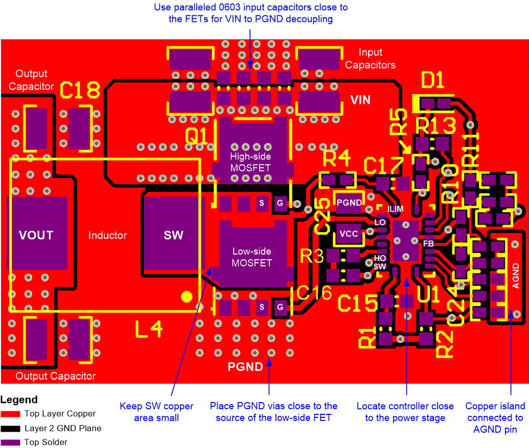
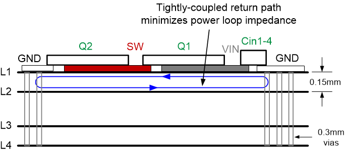
Figure 11-2 shows an example PCB layout based on the LM5146-Q1-EVM12V design. The power component connections are made on the top layer with wide, copper-filled polygon areas. The SW connection from the power MOSFETs to the inductor is purposely kept at minimum area to reduce radiated EMI. A power ground plane is placed on layer 2 with 6 mil (0.15 mm) spacing to the top layer, see Figure 11-3. As a result, the buck regulator hot loop has a small effective area based on this tightly-coupled GND plane directly underneath the MOSFETs.
The LM5146 controller is located close to the gate terminals of the MOSFETs such that the gate drive traces are routed short and direct. Refer to the LM5146-Q1-EVM12V Evaluation Module User's Guide for more detail.
 Figure 11-2 LM5146
Controller PCB Layout (Viewed From Top)