JAJSJI5A December 2020 – January 2023 LM5149
PRODUCTION DATA
- 1 特長
- 2 アプリケーション
- 3 概要
- 4 Revision History
- 5 概要 (続き)
- 6 Pin Configuration and Functions
- 7 Specifications
-
8 Detailed Description
- 8.1 Overview
- 8.2 Functional Block Diagram
- 8.3
Feature Description
- 8.3.1 Input Voltage Range (VIN)
- 8.3.2 High-Voltage Bias Supply Regulator (VCC, VCCX, VDDA)
- 8.3.3 Precision Enable (EN)
- 8.3.4 Power-Good Monitor (PG)
- 8.3.5 Switching Frequency (RT)
- 8.3.6 Active EMI Filter
- 8.3.7 Dual Random Spread Spectrum (DRSS)
- 8.3.8 Soft Start
- 8.3.9 Output Voltage Setpoint (FB)
- 8.3.10 Minimum Controllable On Time
- 8.3.11 Error Amplifier and PWM Comparator (FB, EXTCOMP)
- 8.3.12 Slope Compensation
- 8.3.13 Inductor Current Sense (ISNS+, VOUT)
- 8.3.14 Hiccup Mode Current Limiting
- 8.3.15 High-Side and Low-Side Gate Drivers (HO, LO)
- 8.3.16 Output Configurations (CNFG)
- 8.3.17 Single-Output Dual-Phase Operation
- 8.4 Device Functional Modes
-
9 Application and Implementation
- 9.1 Application Information
- 9.2
Typical Applications
- 9.2.1
Design 1 – High-Efficiency 2.1-MHz Synchronous
Buck Regulator
- 9.2.1.1 Design Requirements
- 9.2.1.2
Detailed Design Procedure
- 9.2.1.2.1 Custom Design With WEBENCH® Tools
- 9.2.1.2.2 Custom Design With Excel Quickstart Tool
- 9.2.1.2.3 Buck Inductor
- 9.2.1.2.4 Current-Sense Resistance
- 9.2.1.2.5 Output Capacitors
- 9.2.1.2.6 Input Capacitors
- 9.2.1.2.7 Frequency Set Resistor
- 9.2.1.2.8 Feedback Resistors
- 9.2.1.2.9 Compensation Components
- 9.2.1.3 Application Curves
- 9.2.2 Design 2 – High Efficiency 48-V to 12-V 400-kHz Synchronous Buck Regulator
- 9.2.3 Design 3 – High Efficiency 440-kHz Synchronous Buck Regulator
- 9.2.4 Design 4 – Dual-Phase 400-kHz 20-A Synchronous Buck Regulator
- 9.2.1
Design 1 – High-Efficiency 2.1-MHz Synchronous
Buck Regulator
- 9.3 Power Supply Recommendations
- 9.4 Layout
- 10Device and Documentation Support
- 11Mechanical, Packaging, and Orderable Information
パッケージ・オプション
メカニカル・データ(パッケージ|ピン)
- RGY|24
サーマルパッド・メカニカル・データ
- RGY|24
発注情報
3 概要
LM5149 は、大電流、シングル出力のアプリケーション向けに対応した、80V の超低静止電流 (IQ) の同期整流降圧 DC/DC コントローラです。本コントローラは、ピーク電流モード制御アーキテクチャを採用しているため、ループ補償が簡単で、過渡応答が高速であり、負荷およびライン・レギュレーションが非常に優れています。LM5149 は、大電流アプリケーション向けに高精度の電流共有を行う、インターリーブ・デュアル位相モードで設定できます。このデバイスは、必要に応じて最低 3.5V の VIN、ほぼ 100% のデューティ・サイクルで動作できます。
LM5149 は、アクティブ EMI フィルタとデュアル・ランダム・スペクトラム拡散 (DRSS) という 2 つの独自の EMI 低減機能を備えています。アクティブ EMI フィルタは、DC 入力バス上のすべてのノイズまたはリップル電圧を検出し、逆位相のキャンセル信号を注入することで、妨害を低減します。DRSS は、低い周波数の三角波変調と高い周波数のランダム変調を組み合わせて、それぞれ低い周波数帯域と高い周波数帯域にわたって EMI を低減します。このハイブリッド手法は、業界標準の EMC テストで規定されている複数分解能帯域幅 (RBW) 設定に適合します。
パッケージ情報
| 部品番号 | パッケージ (1) | 本体サイズ (公称) |
|---|---|---|
| LM5149 | RGY (VQFN、24) | 3.50mm × 5.50mm |
(1) 利用可能なすべてのパッケージについては、このデータシートの末尾にある注文情報を参照してください。
 代表的なアプリケーション回路図
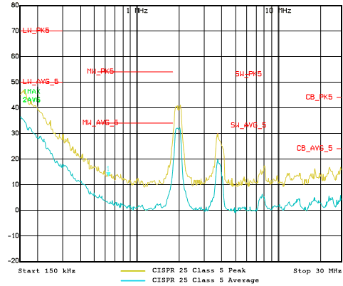
 CISPR
25 EMI 性能 (150kHz~30MHz)