-
LM5163H-Q1 100V、0.5A、10.5μA IQ 接合部温度 165℃の車載用降圧コンバータ
- 1 特長
- 2 アプリケーション
- 3 概要
- 4 Revision History
- 5 Pin Configuration and Functions
- 6 Specifications
-
7 Detailed Description
- 7.1 Overview
- 7.2 Functional Block Diagram
- 7.3
Feature Description
- 7.3.1 Control Architecture
- 7.3.2 Internal VCC Regulator and Bootstrap Capacitor
- 7.3.3 Regulation Comparator
- 7.3.4 Internal Soft Start
- 7.3.5 On-Time Generator
- 7.3.6 Current Limit
- 7.3.7 N-Channel Buck Switch and Driver
- 7.3.8 Synchronous Rectifier
- 7.3.9 Enable/Undervoltage Lockout (EN/UVLO)
- 7.3.10 Power Good (PGOOD)
- 7.3.11 Thermal Protection
- 7.4 Device Functional Modes
- 8 Application and Implementation
- 9 Device and Documentation Support
- 10Mechanical, Packaging, and Orderable Information
- 重要なお知らせ
パッケージ・オプション
メカニカル・データ(パッケージ|ピン)
- DDA|8
サーマルパッド・メカニカル・データ
- DDA|8
発注情報
DATA SHEET
LM5163H-Q1 100V、0.5A、10.5μA IQ 接合部温度 165℃の車載用降圧コンバータ
このリソースの元の言語は英語です。 翻訳は概要を便宜的に提供するもので、自動化ツール (機械翻訳) を使用していることがあり、TI では翻訳の正確性および妥当性につきましては一切保証いたしません。 実際の設計などの前には、ti.com で必ず最新の英語版をご参照くださいますようお願いいたします。
1 特長
- 車載アプリケーション用に AEC-Q100 認定済み
- デバイス温度グレード 1:周囲温度範囲:-40℃~+125℃
- 高信頼性の堅牢なアプリケーション用に設計
- 広い入力電圧範囲:6V~100V
- 接合部温度範囲:-40℃~+165℃
- 165℃対応を確実なものにするサーマル・シャットダウン
- ピークおよびバレー電流制限保護
- 入力 UVLO とソフトスタート (固定 3ms)
- 超低 EMI 要件に最適化
- CISPR 25 class 5 規格に適合
- スケーラブルな車載用電源に最適
- 最小オンおよびオフ時間がわずか 50ns
- 最高 1MHz まで可変のスイッチング周波数
- ダイオード・エミュレーションにより軽負荷時の効率を向上
- 無負荷時の入力静止電流:10.5μA
- シャットダウン時の静止電流:3μA
- 統合によりソリューションのサイズとコストを低減
- COT モード制御アーキテクチャ
- 0.725Ω の NFET 降圧スイッチを内蔵
- 0.34Ω の NFET 同期整流器を内蔵し、外付けのショットキー・ダイオードが不要
- 1.2V の内部基準電圧
- ループ補償部品が不要
- VCC バイアス・レギュレータとブート・ダイオードを内蔵
- WEBENCH® Power Designer を使用してカスタム・レギュレータ設計を作成
3 概要
パワートレイン・システム用の冷却材は高価なものです。メーカーがシステムの冷却材 (水、空気) の使用を減らすことでコストを削減するにつれて、パワートレイン・アプリケーションの周囲温度要件はより高くなっています。また、ADAS (カメラ・モジュール) とパワートレインのシステムは、小さな筐体でもしばしば大きな出力電力を必要とします。これらの要件により、DC/DC コンバータは、高い周囲温度で動作する必要があり、接合部温度は 150℃を超えます。LM5163H-Q1 同期整流降圧コンバータは、最大 165℃の高い接合部温度で動作するように設計されており、高い周囲温度と出力電力の仕様をサポートする高密度ソリューションを実現できます。LM5163H-Q1 は広い入力電圧範囲で動作するため、必要な外付けサージ抑制部品は最小限で済みます。
制御可能な最短のオン時間は 50ns で、大きな降圧率を使用できるため、48V 公称入力から低電圧レールへの直接降圧変換が可能になり、システムの複雑性とソリューションのコストを下げることができます。LM5163H-Q1 は最低 6V の入力電圧ディップ中も動作し、必要に応じて 100% に近いデューティ・サイクルで動作するため、高性能の 48V バッテリ車載用アプリケーションおよび MHEV/EV システムに理想的です。
LM5163H-Q1 は、車載用 AEC-Q100 グレード 1 で要求されるよりも高い温度プロファイルに適合しており、8 ピンの SO PowerPAD™ 集積回路パッケージで供給されます。 このデバイスのピン・ピッチは 1.27mm で、高電圧アプリケーションに適切な間隔を提供します。
パッケージ情報
| 部品番号 | パッケージ(1) | 本体サイズ (公称) |
|---|---|---|
| LM5163H-Q1 | DDA (SO PowerPAD、8) | 4.89mm × 3.90mm |
(1) 利用可能なすべてのパッケージについては、このデータシートの末尾にある注文情報を参照してください。
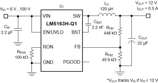
 代表的なアプリケーション
 代表的な応用回路の効率、VOUT = 12V
5 Pin Configuration and Functions
 Figure 5-1 DDA Package8-Pin SO PowerPAD™
Integrated Circuit Package Top View
Figure 5-1 DDA Package8-Pin SO PowerPAD™
Integrated Circuit Package Top ViewTable 5-1 Pin Functions
| PIN | I/O(1) | DESCRIPTION | |
|---|---|---|---|
| NO. | NAME | ||
| 1 | GND | G | Ground connection for internal circuits |
| 2 | VIN | P/I | Regulator supply input pin to high-side power MOSFET and internal bias regulator. Connect directly to the input supply of the buck converter with short, low impedance paths. |
| 3 | EN/UVLO | I | Precision enable and undervoltage lockout (UVLO) programming pin. If the EN/UVLO voltage is below 1.1 V, the converter is in shutdown mode with all functions disabled. If the UVLO voltage is greater than 1.1 V and below 1.5 V, the converter is in standby mode with the internal VCC regulator operational and no switching. If the EN/UVLO voltage is above 1.5 V, the start-up sequence begins. |
| 4 | RON | I | On-time programming pin. A resistor between this pin and GND sets the buck switch on-time. |
| 5 | FB | I | Feedback input of voltage regulation comparator |
| 6 | PGOOD | O | Power good indicator. This pin is an open-drain output pin. Connect to a source voltage through an external pullup resistor between 10 kΩ to 100 kΩ. |
| 7 | BST | P/I | Bootstrap gate-drive supply. Required to connect a high-quality 2.2-nF 50-V X7R ceramic capacitor between BST and SW to bias the internal high-side gate driver. |
| 8 | SW | P | Switching node that is internally connected to the source of the high-side NMOS buck switch and the drain of the low-side NMOS synchronous rectifier. Connect to the switching node of the power inductor. |
| — | EP | — | Exposed pad of the package. No internal electrical connection. Solder the EP to the GND pin and connect to a large copper plane to reduce thermal resistance. |
(1) G = Ground, I = Input, O = Output, P = Power
6 Specifications
6.1 Absolute Maximum Ratings
Over the recommended operating junction temperature range of –40°C to +165°C (unless otherwise noted)(1)
| MIN | MAX | UNIT | ||
|---|---|---|---|---|
| Input voltage | VIN to GND | –0.3 | 100 | V |
| EN to GND | –0.3 | 100 | ||
| FB to GND | –0.3 | 5.5 | ||
| RON to GND | –0.3 | 5.5 | ||
| Bootstrap capacitor | External BST to SW capacitance | 1.5 | 2.5 | nF |
| Output voltage | BST to GND | –0.3 | 105.5 | V |
| BST to SW | –0.3 | 5.5 | ||
| SW to GND | –1.5 | 100 | ||
| SW to GND (20-ns transient) | –3 | |||
| PGOOD to GND | –0.3 | 14 | ||
| Operating junction temperature, TJ | –40 | 165 | °C | |
| Storage temperature, Tstg | –65 | 150 | °C | |
(1) Stresses beyond those listed under Absolute Maximum Ratings may cause permanent damage to the device. These are stress ratings only, which do not imply functional operation of the device at these or any other conditions beyond those indicated under Recommended Operating Conditions. Exposure to absolute-maximum-rated conditions for extended periods may affect device reliability.