JAJSNH1A December 2021 – September 2022 LM5168 , LM5169
PRODUCTION DATA
- 1 特長
- 2 アプリケーション
- 3 概要
- 4 Revision History
- 5 Device Comparison Table
- 6 Pin Configuration and Functions
- 7 Specifications
-
8 Detailed Description
- 8.1 Overview
- 8.2 Functional Block Diagram
- 8.3
Feature Description
- 8.3.1 Control Architecture
- 8.3.2 Internal VCC Regulator and Bootstrap Capacitor
- 8.3.3 Internal Soft Start
- 8.3.4 On-Time Generator
- 8.3.5 Current Limit
- 8.3.6 N-Channel Buck Switch and Driver
- 8.3.7 Synchronous Rectifier
- 8.3.8 Enable, Undervoltage Lockout (EN/UVLO)
- 8.3.9 Power Good (PGOOD)
- 8.3.10 Thermal Protection
- 8.4 Device Functional Modes
-
9 Application and Implementation
- 9.1 Application Information
- 9.2
Typical Fly-Buck™ Converter Application
- 9.2.1 Design Requirements
- 9.2.2
Detailed Design Procedure
- 9.2.2.1 Switching Frequency (RT)
- 9.2.2.2 Transformer Selection
- 9.2.2.3 Output Capacitor Selection
- 9.2.2.4 Secondary Output Diode
- 9.2.2.5 Setting Output Voltage
- 9.2.2.6 Input Capacitor
- 9.2.2.7 Type-3 Ripple Network
- 9.2.2.8 CBST Selection
- 9.2.2.9 Minimum Secondary Output Load
- 9.2.2.10 Example Design Summary
- 9.2.3 Application Curves
- 9.3 Typical Buck Application
- 9.4 Power Supply Recommendations
- 9.5 Layout
- 10Device and Documentation Support
- 11Mechanical, Packaging, and Orderable Information
パッケージ・オプション
メカニカル・データ(パッケージ|ピン)
- DDA|8
サーマルパッド・メカニカル・データ
- DDA|8
発注情報
3 概要
LM5169 および LM5168 同期整流降圧コンバータは、最小限の外部サージ抑制部品で、広い入力電圧範囲のレギュレーションを行えるよう設計されています。制御可能な最短オン時間は 50ns で、大きな降圧率を使用できるため、48V 公称入力から低電圧レールへの直接降圧変換が可能になり、システムの複雑性とソリューションのコストを下げることができます。LM516x は最低 6V の入力電圧ディップ時にも動作し、必要に応じて 100% に近いデューティ・サイクルで動作するため、広い入力電源電圧範囲の産業用および多セルのバッテリ・パック機器に理想的です。
ハイサイドおよびローサイドのパワー MOSFET を内蔵しているため、最大で LM5169 は 0.65A、LM5168 は 0.3A の出力電流を供給します。コンスタント・オン時間 (COT) 制御アーキテクチャにより、スイッチング周波数はほぼ一定で、負荷およびライン過渡応答が非常に優れています。LM516x は、FPWM または自動モード・バージョンが利用できます。FPWM モードにより、負荷範囲の全体にわたって強制連続導通モード (CCM) で動作し、絶縁型 Fly-Buck コンバータ・アプリケーションをサポートします。自動モードにより、非常に低い IQ とダイオード・エミュレーション・モード動作が可能になり、軽負荷時に高効率です。
製品情報
| 部品番号 | パッケージ (1) | 本体サイズ (公称) |
|---|---|---|
| LM5169 | SO PowerPAD (8) | 4.89mm × 3.90mm |
| LM5168 |
(1) 利用可能なパッケージについては、このデータシートの末尾にある注文情報を参照してください。
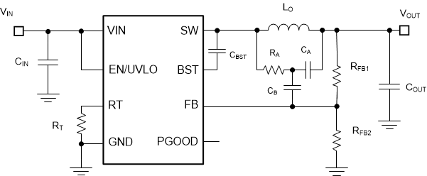
 代表的な降圧アプリケーション回路
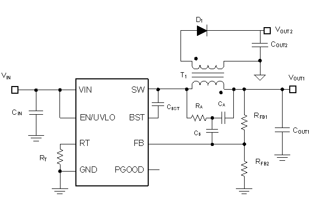
 代表的な Fly-Buck™ コンバータ・アプリケーション回路