-
LM53600/01-Q1 車載用 0.65A/1A、36V、2.1MHz 同期整流式降圧 DC/DC コンバータ JAJSLO9D June 2015 – May 2021 LM53600-Q1 , LM53601-Q1
PRODUCTION DATA
-
LM53600/01-Q1 車載用 0.65A/1A、36V、2.1MHz 同期整流式降圧 DC/DC コンバータ
- 1 特長
- 2 アプリケーション
- 3 概要
- 4 Revision History
- 5 Device Comparison
- 6 Pin Configuration and Functions
- 7 Specifications
- 8 Detailed Description
- 9 Applications and Implementation
- 10Power Supply Recommendations
- 11Layout
- 12Device and Documentation Support
- 13Mechanical, Packaging, and Orderable Information
- 重要なお知らせ
パッケージ・オプション
メカニカル・データ(パッケージ|ピン)
- DSX|10
サーマルパッド・メカニカル・データ
- DSX|10
発注情報
LM53600/01-Q1 車載用 0.65A/1A、36V、2.1MHz 同期整流式降圧 DC/DC コンバータ
1 特長
- 車載アプリケーション認定済み
- 下記内容で AEC-Q100 認定済み
- デバイス温度グレード 1:–40℃~125℃の動作時周囲温度範囲
- デバイス HBM 分類レベル 2
- デバイス CDM 分類レベル C5
- –40℃~150℃の接合部温度範囲 (利用可能)
- 広い動作入力電圧範囲:3.55V~36V (最大 42V の過渡耐性)
- スペクトラム拡散オプションを利用可能
- 固定スイッチング周波数:2.1MHz
- 低い静止電流:23μA
- シャットダウン電流:1.8μA
- 可変、3.3V、5V の出力
- 最大電流負荷:650mA (LM53600-Q1)、1000mA (LM53601-Q1)
- 強制 PWM モードをピンにより選択可能
- フィルタと遅延リリースを備えた RESET 出力
- 外部周波数同期
- 補償、ソフトスタート、電流制限、UVLO を内蔵
- ウェッタブル・フランクまたは非ウェッタブル・フランク 10 ピン、3mm × 3mm SON パッケージ
3 概要
LM53600-Q1 および LM53601-Q1 同期整流式降圧レギュレータ・デバイスは車載用アプリケーションに最適化されており、5V、3.3V、可変出力のいずれかを出力します。LM53600-Q1 は最大 650mA、LM53601-Q1 は最大 1000mA の負荷電流をサポートしています。高度な高速回路により、LM53600-Q1 および LM53601-Q1 デバイスは 2.1MHz の固定周波数で 18V の入力から 3.3V の出力をレギュレートできます。革新的なアーキテクチャにより、本デバイスはわずか 3.8V の入力電圧で 3.3V の出力をレギュレートできます。最大 36V の入力電圧範囲は最大 42V の過渡耐性を備えているため、入力サージ保護設計が簡単です。フィルタ機能と遅延リリースを備えたオープン・ドレインのリセット出力により、真のシステム・ステータス表示を実現できます。この機能により、追加のスーパーバイザ部品が必要なくなるため、コストと基板面積を削減できます。PWM モードと PFM モードとのシームレスな移行、および静止電流がわずか 23µA であることから、あらゆる負荷で高い効率と優れた過渡応答が保証されます。外付け部品がほとんど不要であるため、コンパクトな PCB レイアウトを生成できます。LM53600-Q1 および LM53601-Q1 デバイスは Q1 に格付けされており、–40℃~150℃の接合部温度範囲にわたって電気的特性が保証されています。
| 部品番号 | パッケージ(1) | 本体サイズ (公称) |
|---|---|---|
| LM53600-Q1 | WSON (10) | 3.00mm × 3.00mm |
| LM53601-Q1 |
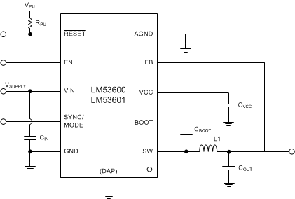
 概略回路図 – 固定出力
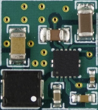
 車載用の 11.2mm x 12.7mm のレイアウト
4 Revision History
Changes from Revision C (April 2021) to Revision D (May 2021)
- 非ウェッタブル・フランク・オプションを追加Go
Changes from Revision B (February 2016) to Revision C (April 2021)
- 文書全体にわたって表、図、相互参照の採番方法を更新Go
Changes from Revision A (December 2015) to Revision B (February 2016)
- Updated tables in the Device Comparison Table Go
- Removed last sentence in SYNC/MODE description in Pin Functions table in Pin Configuration and Functions Go
- Updated IB Parameter in Section 7.5 tableGo
- Changed RRESET MAX from "80" to "120" in Section 7.5 tableGo
- Changed Vout to Vout_3_3V, Vout_5V, and Vout_ADJ for 3.3-V, 5-V, and ADJ output voltage options in Section 7.6 tableGo
- Corrected references for SNAU190 and SNAU191 in Section 12.1.1 Go
Changes from Revision * (June 2015) to Revision A (December 2015)
- デバイスのステータスを「製品プレビュー」から「量産データ」に変更Go
5 Device Comparison
| Part Number(1) | Output Voltage | Spread Spectrum | Package Qty (2) | Wettable (WF)/Non-Wettable Flanks (non-WF) |
|---|---|---|---|---|
| LM53600AQDSXRQ1 | Adjustable | No | 3000 | WF |
| LM53600AQDSXTQ1 | Adjustable | No | 250 | WF |
| LM536003QDSXRQ1 | 3.3 V | No | 3000 | WF |
| LM536003QDSXTQ1 | 3.3 V | No | 250 | WF |
| LM536005QDSXRQ1 | 5.0 V | No | 3000 | WF |
| LM536005QDSXTQ1 | 5.0 V | No | 250 | WF |
| LM53600MQDSXRQ1 | Adjustable | Yes | 3000 | WF |
| LM53600MQDSXTQ1 | Adjustable | Yes | 250 | WF |
| LM53600NQDSXRQ1 | 3.3 V | Yes | 3000 | WF |
| LM53600NQDSXTQ1 | 3.3 V | Yes | 250 | WF |
| LM53600LQDSXRQ1 | 5.0 V | Yes | 3000 | WF |
| LM53600LQDSXTQ1 | 5.0 V | Yes | 250 | WF |
| LM53600MQUDSXRQ1 | Adjustable | Yes | 3000 | Non-WF |
| Part Number(1) | Output Voltage | Spread Spectrum | Package Qty (2) | Wettable (WF)/Non-Wettable Flanks (non-WF) |
|---|---|---|---|---|
| LM53601AQDSXRQ1 | Adjustable | No | 3000 | WF |
| LM53601AQDSXTQ1 | Adjustable | No | 250 | WF |
| LM536013QDSXRQ1 | 3.3 V | No | 3000 | WF |
| LM536013QDSXTQ1 | 3.3 V | No | 250 | WF |
| LM536015QDSXRQ1 | 5.0 V | No | 3000 | WF |
| LM536015QDSXTQ1 | 5.0 V | No | 250 | WF |
| LM53601MQDSXRQ1 | Adjustable | Yes | 3000 | WF |
| LM53601MQDSXTQ1 | Adjustable | Yes | 250 | WF |
| LM53601NQDSXRQ1 | 3.3 V | Yes | 3000 | WF |
| LM53601NQDSXTQ1 | 3.3 V | Yes | 250 | WF |
| LM53601LQDSXRQ1 | 5.0 V | Yes | 3000 | WF |
| LM53601LQDSXTQ1 | 5.0 V | Yes | 250 | WF |
| LM536015QUDSXRQ1 | 5.0 V | No | 3000 | Non-WF |
| LM536013QUDSXRQ1 | 3.3 V | No | 3000 | Non-WF |
| LM53601MQUDSXRQ1 | Adjustable | Yes | 3000 | Non-WF |
6 Pin Configuration and Functions
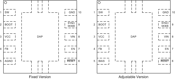
 Figure 6-1 DSX Package10-Pin WSONTop View
| PIN | TYPE(1) | DESCRIPTION | |
|---|---|---|---|
| NO. | NAME | ||
| 1 | SW | P | Regulator switch node. Connect to output inductor. |
| 2 | BOOT | I | High side gate driver upper supply rail. Connect a 100-nF capacitor from SW pin to BOOT. An internal diode charges the capacitor while SW node is low. |
| 3 | VCC | P | Internal 3-V regulator output. Used as supply to internal control circuits. Connect a high quality 1.0-μF capacitor from this pin to AGND for fixed versions or to GND for adjustable versions. |
| 4 | FB (Fixed Versions) | I/P | Fixed version only, this pin serves as feedback for output voltage as well as power source for VCC’s regulator. Connect to output node. Place 10-nF bypass capacitor immediately adjacent to this pin. |
| FB (ADJ Version) | I | ADJ version only, this pin serves as feedback for output voltage only. Connect to output through a voltage divider which determines output voltage set point. | |
| 5 | AGND (Fixed Version) | G | Fixed versions only, this is the ground to which input signals and FB are compared. |
| BIAS (ADJ Version) | P | Power source for VCC’s regulator. Connect to output node. Place 10-nF bypass capacitor immediately adjacent to this pin. | |
| 6 | RESET | O | Open drain reset output. Connect to suitable voltage supply through a current limiting pull up resistor. High = regulator OK, Low = regulator fault. Will go low when EN = low. See Detailed Description. |
| 7 | EN | I | Enable input to regulator. High = on, Low = off. Can be connected to Vin. Do not float. |
| 8 | VIN | I | Input supply to regulator. Connect input bypass capacitors directly between this pin and GND. |
| 9 | SYNC/MODE | I | This is a multifunction mode control input which is tolerant of voltages up to input voltage. With a valid synchronization signal at this pin, the device will switch in forced PWM mode at the external clock frequency and synchronize with it at the rising edge of the clock. See the Electrical Characteristics for synchronization signal specifications. With this input tied high, the device will switch at the internal clock frequency in forced PWM mode. With this input tied low, the device will switch at the internal clock frequency in AUTO mode with diode emulation at light load. Spread spectrum is disabled if there is a valid synchronization signal. Do not float. |
| 10 | GND | G | Bypass to VIN immediately adjacent to this pin. |
| DAP (EXPOSED PAD) | Thermal, GND | Thermal | Connect to ground – The sole function of the DAP interface is the thermal improvement of the device, a direct thermal connection to a ground plane is required. The DAP is not meant as an electrical interconnect. Electrical characteristics are not ensured. |