JAJSM35B December 2015 – July 2021 LM53625-Q1 , LM53635-Q1
PRODUCTION DATA
- 1 特長
- 2 アプリケーション
- 3 概要
- 4 Revision History
- 5 Device Comparison
- 6 Pin Configuration and Functions
- 7 Specifications
- 8 Detailed Description
-
9 Application and Implementation
- 9.1 Application Information
- 9.2
Typical Applications
- 9.2.1 General Application
- 9.2.2 Fixed 5-V Output for USB-Type Applications
- 9.2.3 Fixed 3.3-V Output
- 9.2.4 Adjustable Output
- 9.3 What to Do and What Not to Do
- 10Power Supply Recommendations
- 11Layout
- 12Device and Documentation Support
- 13Mechanical, Packaging, and Orderable Information
パッケージ・オプション
デバイスごとのパッケージ図は、PDF版データシートをご参照ください。
メカニカル・データ(パッケージ|ピン)
- RNL|22
サーマルパッド・メカニカル・データ
- RNL|22
発注情報
9.2.3.3 Application Curves
The following characteristics apply only to the circuit of Figure 9-18. These parameters are not tested and represent typical performance only. Unless otherwise stated, the following conditions apply: VIN = 12 V, TA = 25°C. For the purpose of offering the more information to the designer, information for the application with FPWM pin high (FPWM mode) and FPWM pin low (AUTO mode) is included, although the schematic shows the application running specifically in AUTO mode. The mode is specified under each of the following graphs.
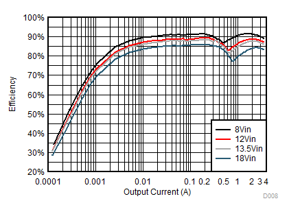
| VOUT = 3.3 V | AUTO |
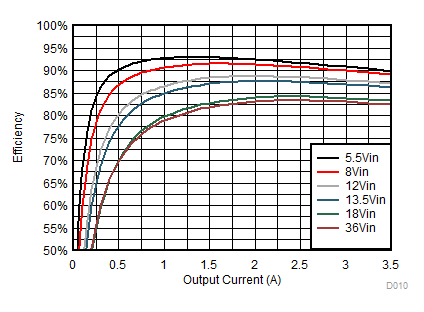
| VOUT = 3.3 V | FPWM |
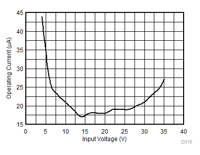
| VOUT = 3.3 V | AUTO | IOUT = 0A |
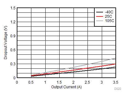
| VOUT = 3.3 V |
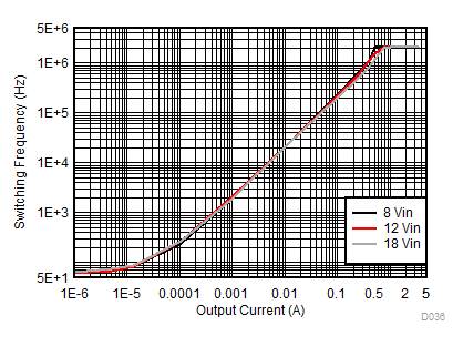
| VOUT = 3.3 V | AUTO |
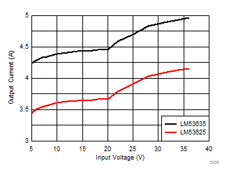
| VOUT = 3.3 V | L=2.2 µH | IOUT = 1 A |
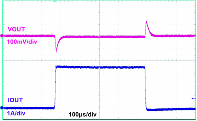
| FPWM | VOUT = 3.3 V | L = 2.2 µH, |
| COUT = 3 × 22 µF | IOUT = 0 A to 3.5 A | TR = TF = 1 µs |
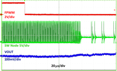
| VOUT = 3.3 V | IOUT = 10 mA |
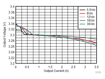
| VOUT = 3.3 V | AUTO |
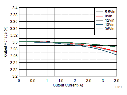
| VOUT = 3.3 V | FPWM |
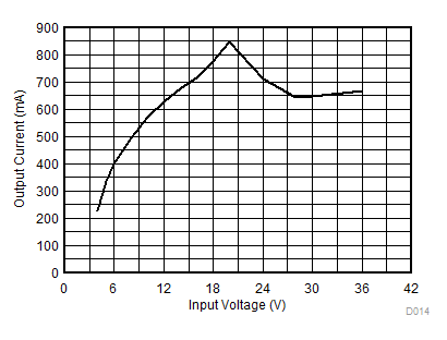
| VOUT = 3.3 V |
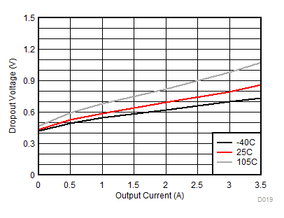
| VOUT = 3.3 V |
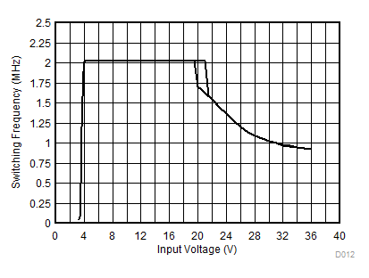
| VOUT = 3.3 V | FPWM | IOUT = 1 A |
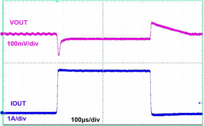
| AUTO | VOUT = 3.3 V | L = 2.2 µH, |
| COUT = 3 × 22 µF | IOUT = 0 A to 3.5 A | TR = TF = 1 µs |
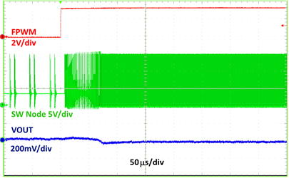
| VOUT = 3.3 V | IOUT = 10 mA | |