JAJSFM3E February 2015 – June 2018 LMH1218
PRODUCTION DATA.
- 1 特長
- 2 アプリケーション
- 3 概要
- 4 改訂履歴
- 5 概要(続き)
- 6 Pin Configuration and Functions
- 7 Specifications
-
8 Detailed Description
- 8.1 Overview
- 8.2 Functional Block Diagram
- 8.3
Feature Description
- 8.3.1 Loss of Signal Detector
- 8.3.2 Continuous Time Linear Equalizer (CTLE)
- 8.3.3 2:1 Multiplexer
- 8.3.4 Clock and Data Recovery
- 8.3.5 Eye Opening Monitor (EOM)
- 8.3.6 Fast EOM
- 8.3.7 LMH1218 Device Configuration
- 8.3.8 Power-On Reset
- 8.4 Device Functional Modes
- 8.5 Programming
- 8.6 Register Maps
- 9 Application and Implementation
- 10Power Supply Recommendations
- 11Layout
- 12デバイスおよびドキュメントのサポート
- 13メカニカル、パッケージ、および注文情報
パッケージ・オプション
メカニカル・データ(パッケージ|ピン)
- RTW|24
サーマルパッド・メカニカル・データ
- RTW|24
発注情報
8.3.7.6 SMBus READ/WRITE Transaction
The System Management Bus (SMBus) is a two-wire serial interface through which various system component chips can communicate with the master. Slave devices are identified by having a unique device address. The two-wire serial interface consists of SCL and SDA signals. SCL is a clock output from the Master to all of the Slave devices on the bus. SDA is a bidirectional data signal between the Master and Slave devices. The LMH1218 SMBUS SCL and SDA signals are open drain and require external pull up resistors.
Start and Stop:
The Master generates Start and Stop conditions at the beginning and end of each transaction.
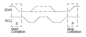
- Start: High to low transition (falling edge) of SDA while SCL is high
- Stop: Low to high transition (rising edge) of SDA while SCL is high
 Figure 9. Start and Stop Conditions
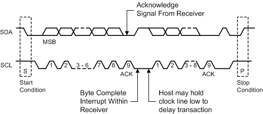
 The Master generates 9 clock pulses for each byte transfer. The 9th clock pulse constitutes the ACK cycle. The transmitter releases SDA to allow the receiver to send the ACK signal. An ACK is when the device pulls SDA low, while a NACK is recorded if the line remains high.
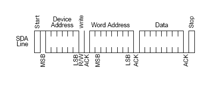
Writing data from a master to a slave comprises of 3 parts as noted in figure Figure 11
- The master begins with start condition followed by the slave device address with the R/W bit cleared
- The 8-bit register address that will be written
- The data byte to write

SMBus read operation consists of four parts
- The master initiates the read cycle with start condition followed by slave device address with the R/W bit cleared
- The 8-bit register address that is to be read
- After acknowledgment from the slave, the master initiates a re-start condition
- The slave device address is resent followed with R/W bit set
- After acknowledgment from the slave, the data is read back from the slave to the master. The last ACK is high if there are no more bytes to read
 Figure 12. SMBus Read Operation
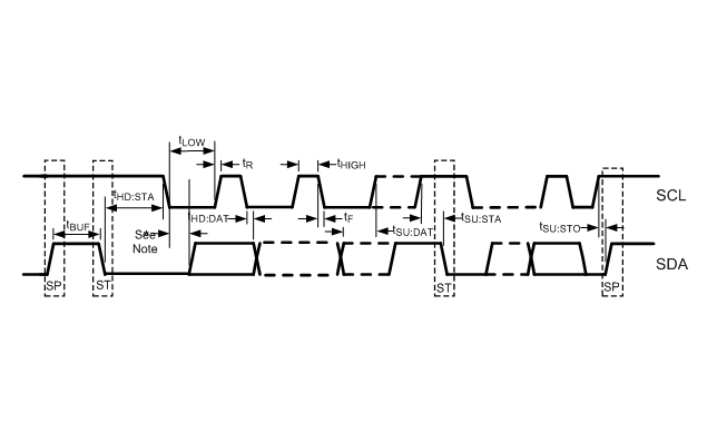
  Figure 13. SMBus Timing Parameters