JAJSEU5D October 2014 – February 2018 LMH5401
PRODUCTION DATA.
- 1 特長
- 2 アプリケーション
- 3 概要
- 4 改訂履歴
- 5 Pin Configuration and Functions
-
6 Specifications
- 6.1 Absolute Maximum Ratings
- 6.2 ESD Ratings
- 6.3 Recommended Operating Conditions
- 6.4 Thermal Information
- 6.5 Electrical Characteristics: VS = 5 V
- 6.6 Electrical Characteristics: VS = 3.3 V
- 6.7 Typical Characteristics: 5 V
- 6.8 Typical Characteristics: 3.3 V
- 6.9 Typical Characteristics: 3.3-V to 5-V Supply Range
- 7 Parameter Measurement Information
- 8 Detailed Description
-
9 Application and Implementation
- 9.1 Application Information
- 9.2 Typical Application
- 9.3 Do's and Don'ts
- 10Power Supply Recommendations
- 11Layout
- 12デバイスおよびドキュメントのサポート
- 13メカニカル、パッケージ、および注文情報
9.1.3 Noise Analysis
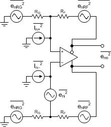
The first step in the output noise analysis is to reduce the application circuit to the simplest form with equal feedback and gain setting elements to ground (as shown in Figure 64) and considering FAD and resistor noise terms.
 Figure 64. FDA Noise-Analysis Circuit
Figure 64 shows the noise powers for each term. When the RF and RG terms are matched on each side, the total differential output noise is the root sum of squares (RSS) of these separate terms. Using NG (noise gain) ≡ 1 + RF / RG, the total output noise is shown in Equation 8. Each resistor noise term is a 4-kTR power.

The first term is the differential input spot noise times the noise gain. The second term is the input current noise terms times the feedback resistor (and because there are two terms, the power is two times one of the terms). The last term is the output noise resulting from the RF and RG resistors (again times two) for the output noise power of each side added together. Using the exact values for a 50-Ω, matched, single-ended to differential gain, sweep with 127 Ω (plus an internal 25 Ω) and the intrinsic noise eni = 1.25 nV and in = 3.5 pA for the LMH5401, which gives an output spot noise from Equation 8. Then, dividing by the signal gain set through internal resistors (AV), gives the input-referred, spot-noise voltage (ei) of 1.35 nV/√Hz. Note that for the LMH5401 the current noise is an insignificant noise contributor because of the low value of RF.