JAJSH77L January 2010 – April 2019 LMZ10503
PRODUCTION DATA.
- 1 特長
- 2 アプリケーション
- 3 概要
- 4 改訂履歴
- 5 Pin Configuration and Functions
- 6 Specifications
- 7 Detailed Description
- 8 Application and Implementation
- 9 Power Supply Recommendations
- 10Layout
- 11デバイスおよびドキュメントのサポート
- 12メカニカル、パッケージ、および注文情報
5 Pin Configuration and Functions
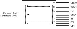
NDW Package
7-Lead TO-PMOD
Top View

Pin Functions
| PIN | TYPE | DESCRIPTION | |
|---|---|---|---|
| NAME | NO. | ||
| EN | 2 | Analog | Active-high enable input for the device. |
| Exposed Pad | — | Ground | Exposed pad is used as a thermal connection to remove heat from the device. Connect this pad to the PCB ground plane in order to reduce thermal resistance value. EP must also provide a direct electrical connection to the input and output capacitors ground terminals. Connect EP to pin 4. |
| FB | 5 | Analog | Feedback pin. This is the inverting input of the error amplifier used for sensing the output voltage. Keep the copper area of this node small. |
| GND | 4 | Ground | Power ground and signal ground. Provide a direct connection to the EP. Place the bottom feedback resistor as close as possible to GND and FB pin. |
| SS | 3 | Analog | Soft-start control pin. An internal 2-µA current source charges an external capacitor connected between SS and GND pins to set the output voltage ramp rate during startup. The SS pin can also be used to configure the tracking feature. |
| VIN | 1 | Power | Power supply input. A low ESR input capacitance should be located as close as possible to the VIN pin and exposed pad (EP). |
| VOUT | 6, 7 | Power | The output terminal of the internal inductor. Connect the output filter capacitor between VOUT pin and EP. |