JAJSG01D June 2012 – August 2018 LMZ20502
PRODUCTION DATA.
- 1 特長
- 2 アプリケーション
- 3 概要
- 4 改訂履歴
- 5 Pin Configuration and Functions
- 6 Specifications
- 7 Detailed Description
- 8 Application and Implementation
- 9 Power Supply Recommendations
- 10Layout
- 11デバイスおよびドキュメントのサポート
- 12メカニカル、パッケージ、および注文情報
パッケージ・オプション
デバイスごとのパッケージ図は、PDF版データシートをご参照ください。
メカニカル・データ(パッケージ|ピン)
- SIL|8
サーマルパッド・メカニカル・データ
発注情報
7.3.6 Power Good Flag Function
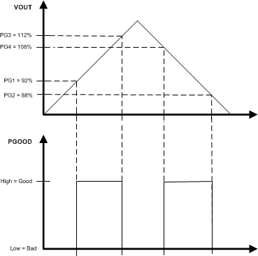
The operation of the power good flag function is described in the diagram shown in Figure 13.
 Figure 13. Typical Power Good Flag Operation
 This output consists of an open drain NMOS with an Rdson of about 70 Ω. When used, the power good flag should be connected to a logic supply through a pull-up resistor. It can also be pulled-up to either VIN or VOUT, through an appropriate resistor, as desired. If this function is not needed, the PG output should be left floating. The current through this flag pin should be limited to less than 4 mA. A pull-up resistor of ≥1.5 kΩ will satisfy this requirement. When the EN input is pulled low, the PG flag output will also be forced low, assuming a valid input voltage is present at the VIN pin.