SNVS095F May 2004 – March 2015 LP2952-N , LP2953
PRODUCTION DATA.
- 1 Features
- 2 Applications
- 3 Description
- 4 Revision History
- 5 Pin Configuration and Functions
- 6 Specifications
- 7 Detailed Description
-
8 Application and Implementation
- 8.1 Application Information
- 8.2
Typical Applications
- 8.2.1 Basic 5-V Regulator
- 8.2.2 5-V Current Limiter with Load Fault Indicator
- 8.2.3 Low Temperature Coefficient Current Sink
- 8.2.4 5-V Regulator With Error Flags for Low Battery and Out of Regulation
- 8.2.5 5-V Battery Powered Supply With Backup and Low Battery Flag
- 8.2.6 5-V Regulator With Timed Power-On Reset
- 8.2.7 5-V Regulator With Snap-ON and Snap-OFF Features and Hysteresis
- 8.2.8 5-V Regulator With Error Flags for Low Battery and Out of Regulation With Snap-ON or Snap-OFF Output
- 8.2.9 5-V Regulator With Timed Power-On Reset, Snap-ON and Snap-OFF Features, and Hysteresis
- 9 Power Supply Recommendations
- 10Layout
- 11Device and Documentation Support
- 12Mechanical, Packaging, and Orderable Information
1 Features
- 2.3-V to 30-V Input Voltage Range
- Output Voltage Adjusts from 1.23 V to 29 V
- 250-mA Output Current
- Extremely Low Quiescent Current
- Low Dropout Voltage
- Extremely Tight Line and Load Regulation
- Very Low Temperature Coefficient
- Current and Thermal Limiting
- Reverse Battery-Input Protection
- 50-mA (Typical) Automatic Output Discharge
- LP2953 Versions Only
- Auxiliary Comparator Included With CMOS- and TTL-Compatible Output Levels. Can Be Used for Fault Detection, Low-Input Line Detection, and so on.
2 Applications
- High-Efficiency Linear Regulator
- Regulator With Undervoltage Shutdown
- Low-Dropout Battery-Powered Regulator
- Snap-ON/Snap-OFF Regulator
3 Description
The LP2952 and LP2953 are micropower voltage regulators with very low quiescent current (130 μA typical at 1-mA load) and very low dropout voltage (typically 60 mV at light load and 470 mV at 250-mA load current). They are ideally suited for battery-powered systems. Furthermore, the quiescent current increases only slightly at dropout, which prolongs battery life.
The LP2952 and LP2953 retain all the desirable characteristics of the LP2951, but offer increased output current, additional features, and an improved shutdown function.
The automatic output discharge pulls the output down quickly when the shutdown is activated.
The error flag goes low if the output voltage drops out of regulation.
Reverse battery-input protection is provided.
The internal voltage reference is made available for external use, providing a low temperature coefficient (20 ppm/°C) reference with very good line (0.03%) and load (0.04%) regulation.
Device Information(1)
| PART NUMBER | PACKAGE | BODY SIZE (NOM) |
|---|---|---|
| LP2952x | SOIC (16) | 9.90 mm × 3.91 mm |
| LP2953x | SOIC (16) | 9.90 mm × 3.91 mm |
| PDIP (16) | 21.755 mm × 6.35 mm |
- For all available packages, see the orderable addendum at the end of the data sheet.
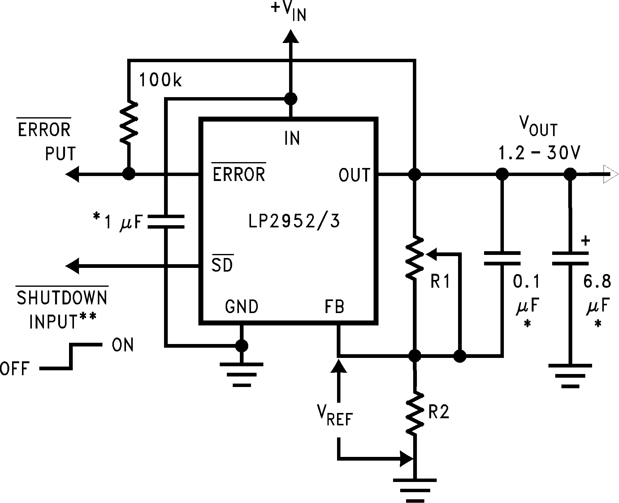
Typical Application Schematic
