JAJSAB5F December 2006 – November 2016 LP38853
PRODUCTION DATA.
- 1 特長
- 2 アプリケーション
- 3 概要
- 4 改訂履歴
- 5 Pin Configuration and Functions
- 6 Specifications
- 7 Detailed Description
- 8 Application and Implementation
- 9 Power Supply Recommendations
- 10Layout
- 11デバイスおよびドキュメントのサポート
- 12メカニカル、パッケージ、および注文情報
- 12メカニカル、パッケージ、および注文情報
パッケージ・オプション
メカニカル・データ(パッケージ|ピン)
サーマルパッド・メカニカル・データ
発注情報
6.7 Typical Characteristics
Refer to the 概略回路図. Unless otherwise specified: TJ = 25°C, R1 = 1.4 kΩ, R2 = 1 kΩ, CFF= 0.01 µF, VIN = VOUT(NOM) + 1 V, VBIAS = 3 V, IOUT = 10 mA, CIN = 10-µF ceramic, COUT = 10-µF ceramic, CBIAS = 1-µF ceramic, CSS = open.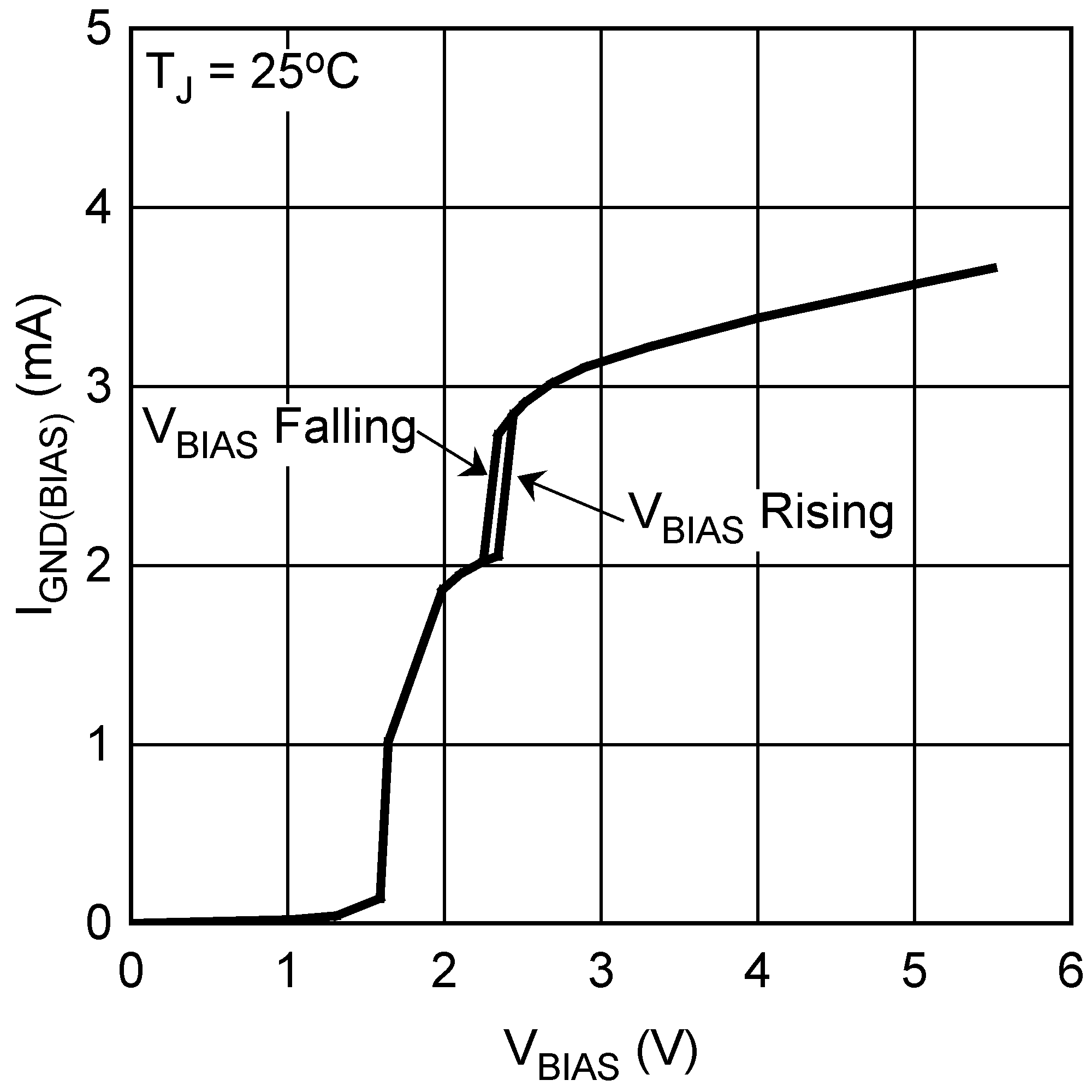 Figure 1. BIAS Ground Pin Current (IGND(BIAS)) vs VBIAS
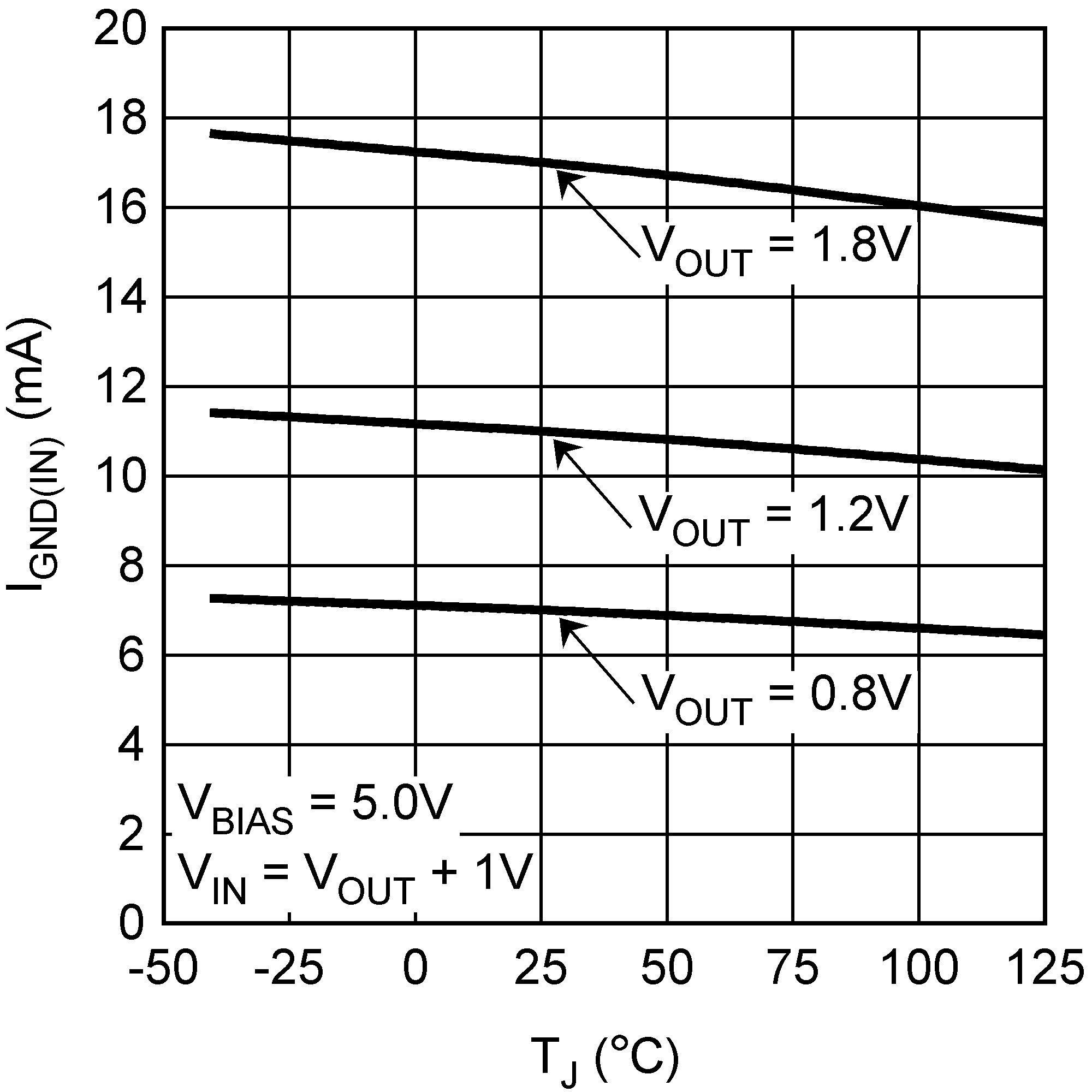 Figure 3. IN Ground Pin Current vs Temperature
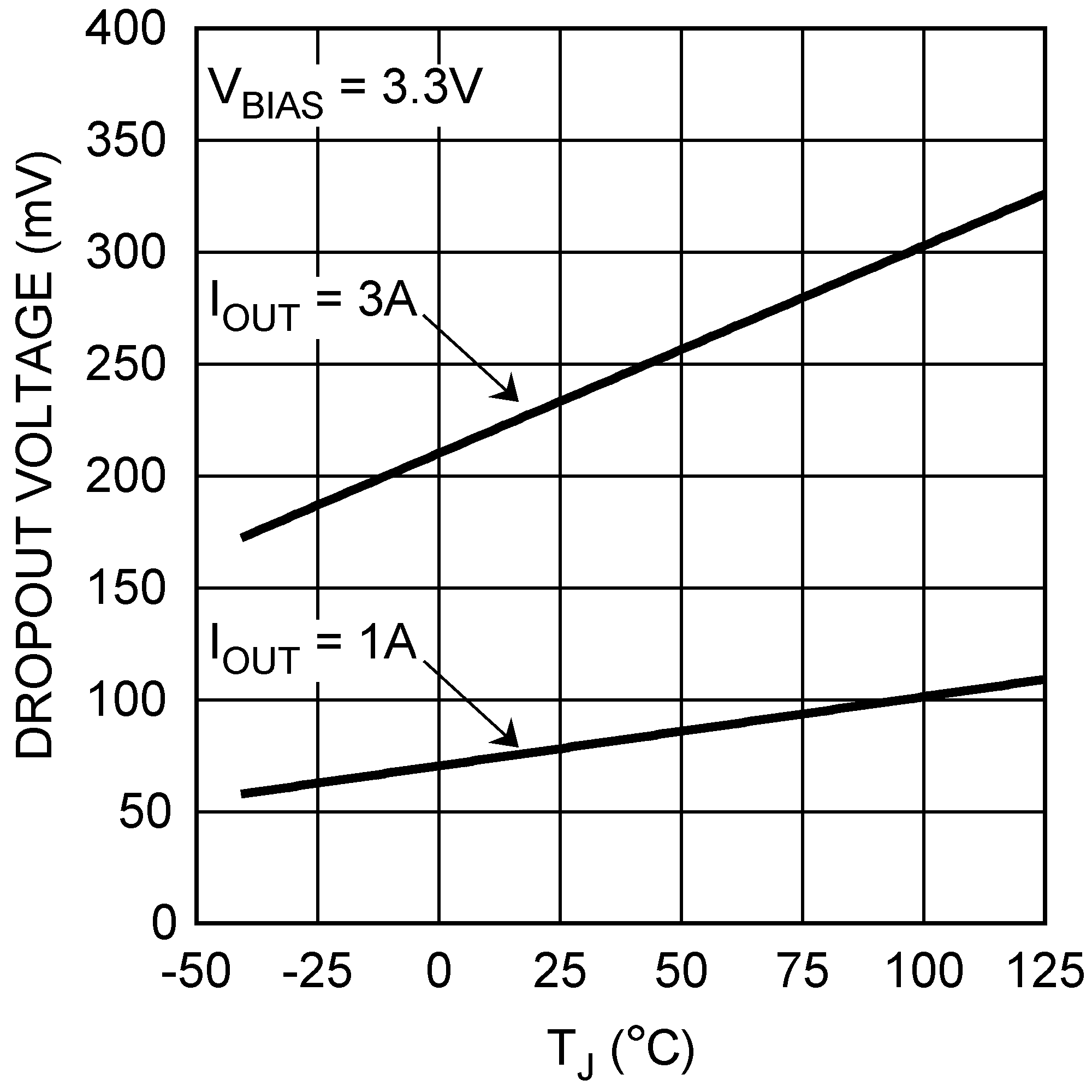 Figure 5. Dropout Voltage (VDO) vs Temperature
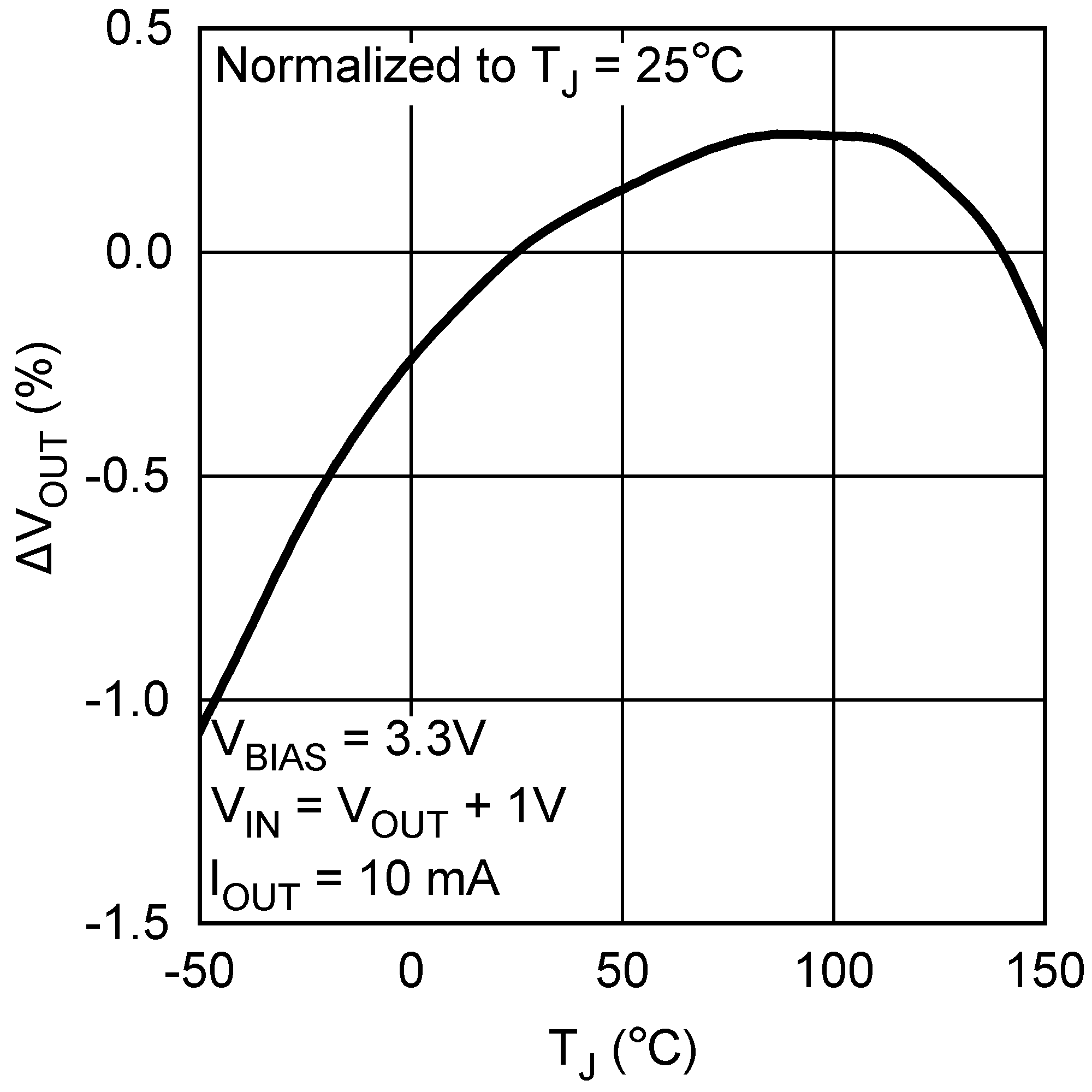 Figure 7. VOUT vs Temperature
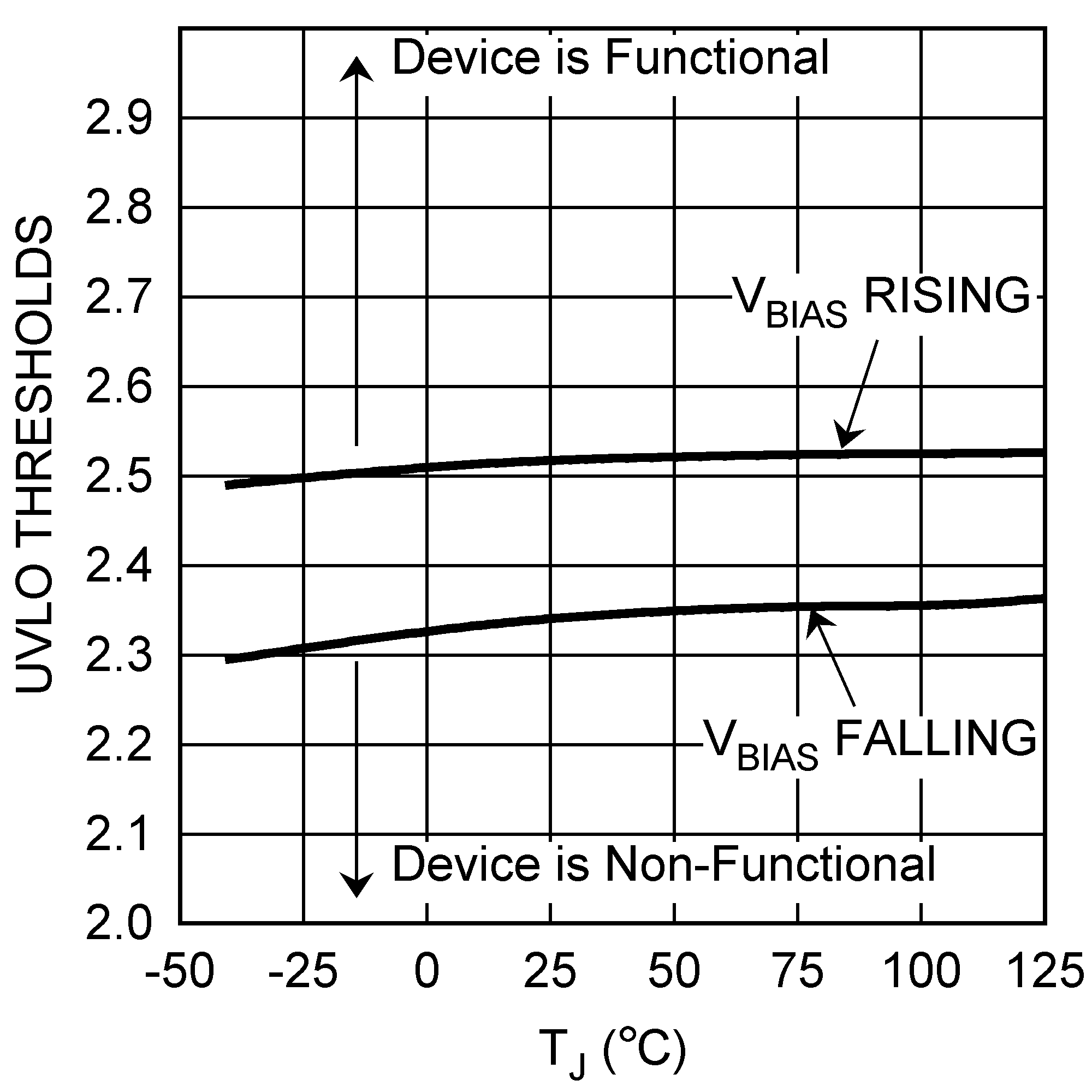 Figure 9. UVLO Thresholds vs Temperature
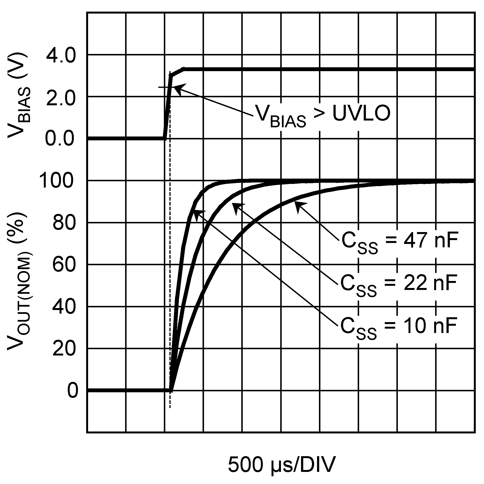
| 10 nF to 47 nF |
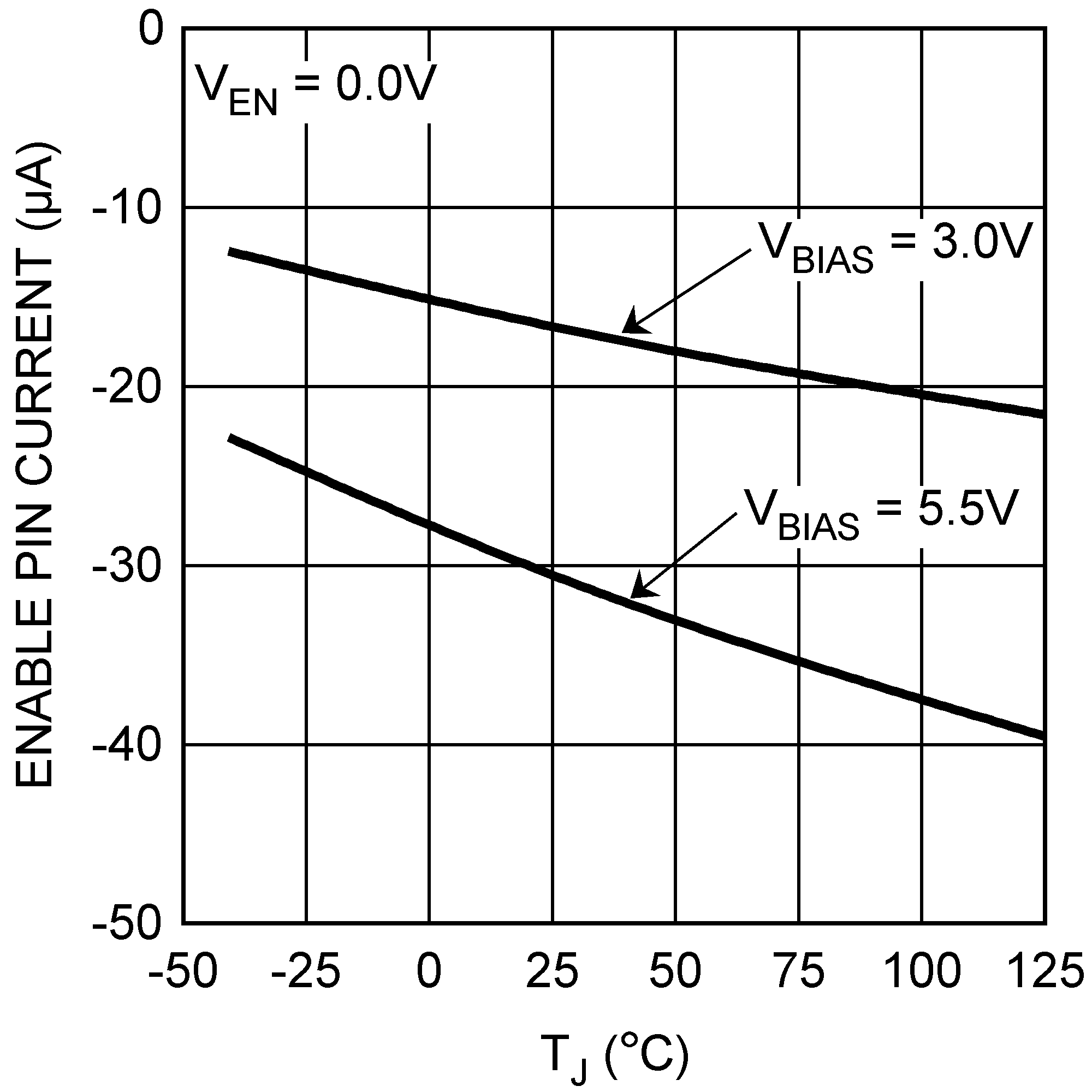
Figure 13. Enable Pulldown Current (IEN) vs Temperature
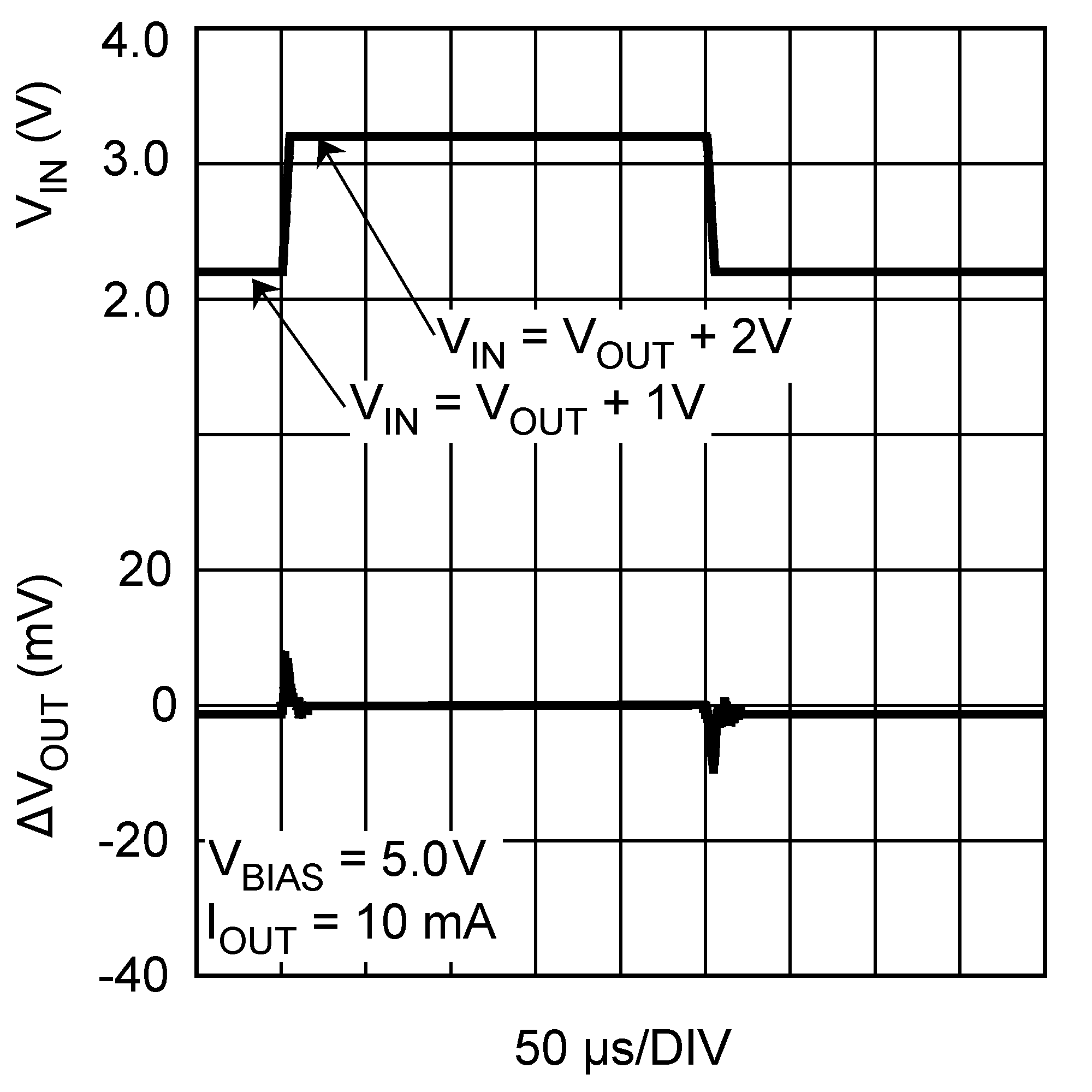
Figure 15. VIN Line Transient Response
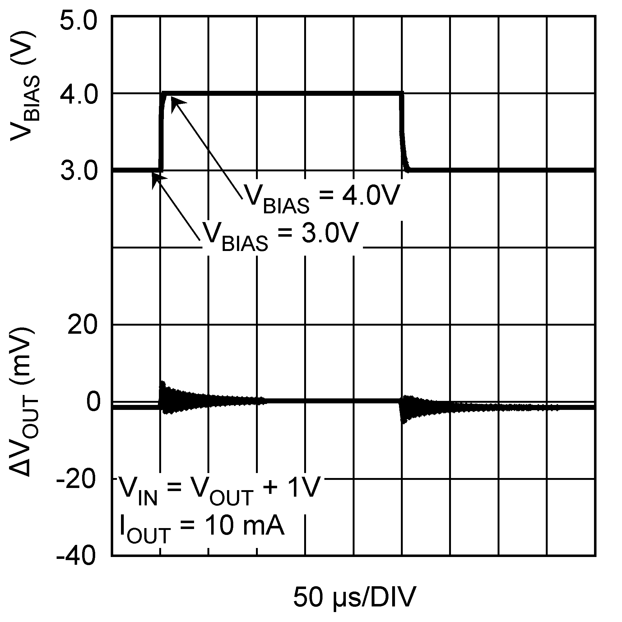
Figure 17. VBIAS Line Transient Response
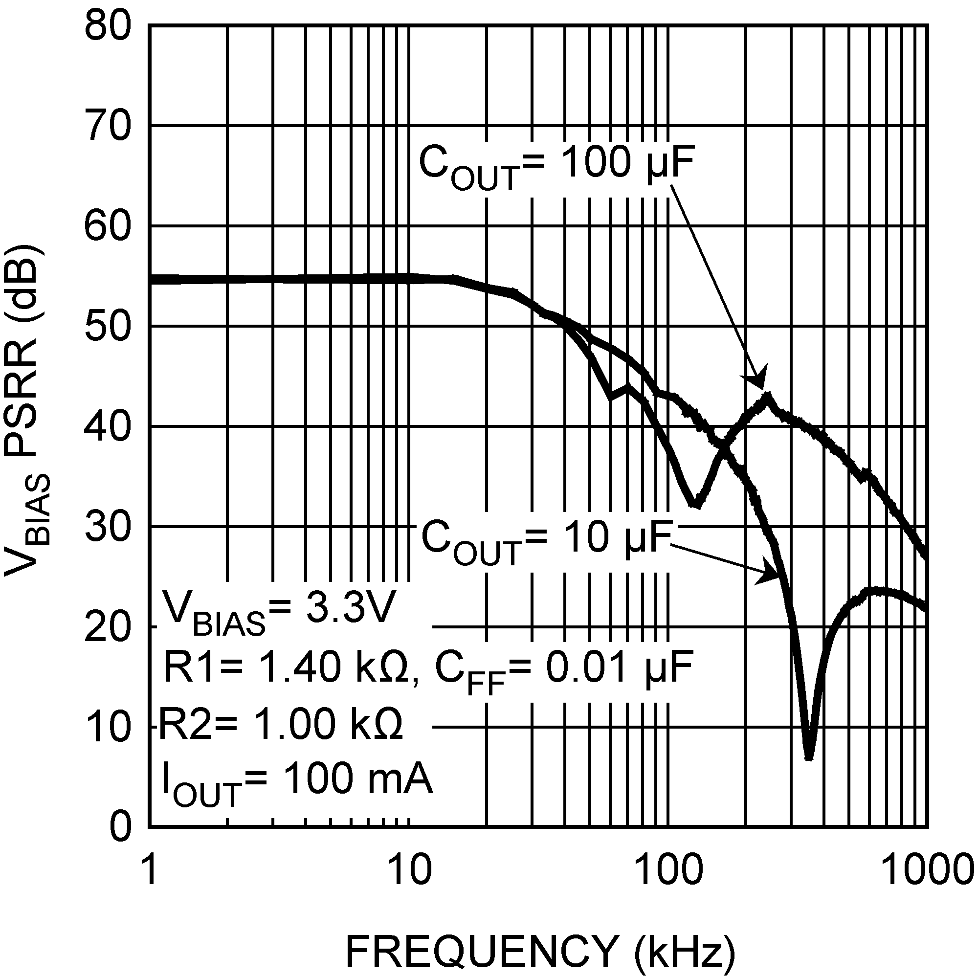
Figure 19. VBIAS PSRR
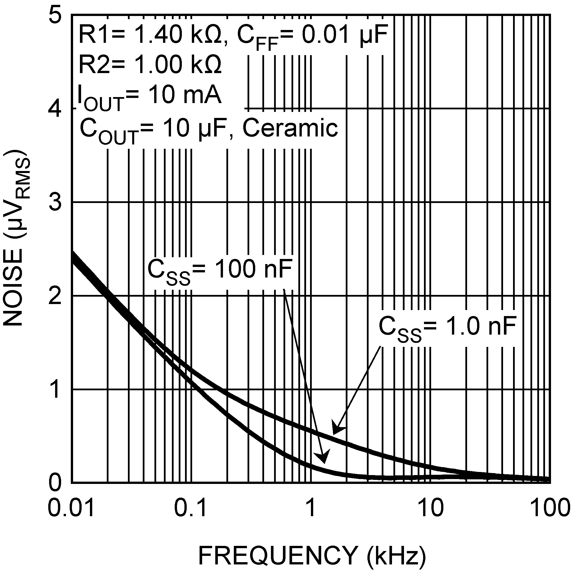
Figure 21. Output Noise
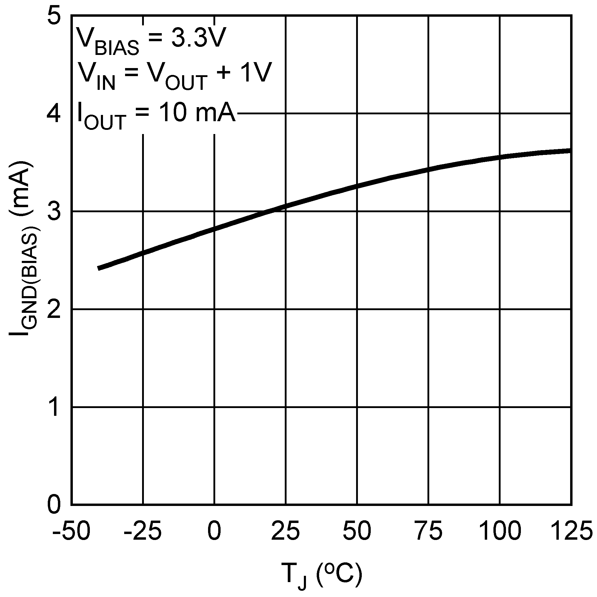 Figure 2. BIAS Ground Pin Current (IGND(BIAS)) vs Temperature
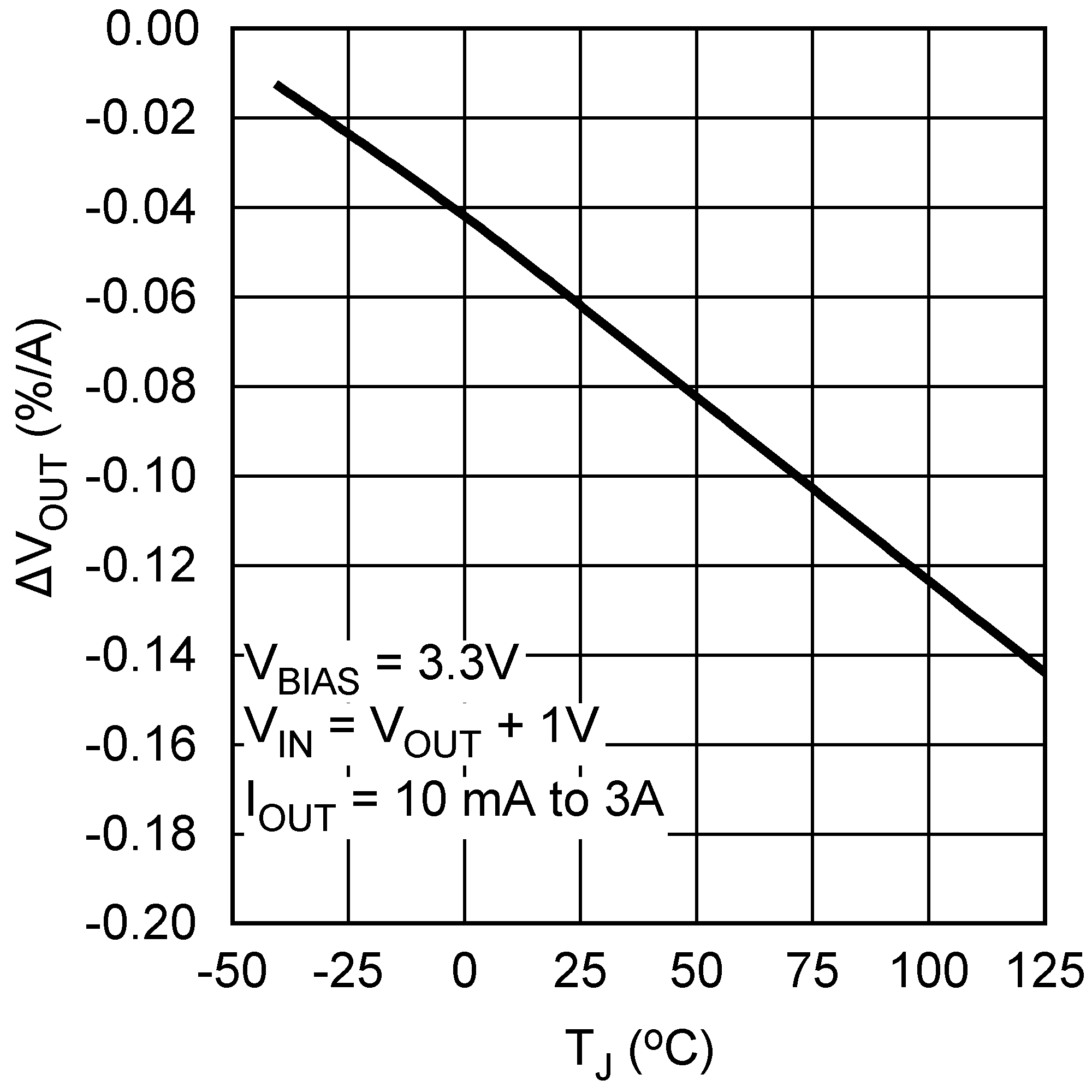 Figure 4. Load Regulation vs Temperature
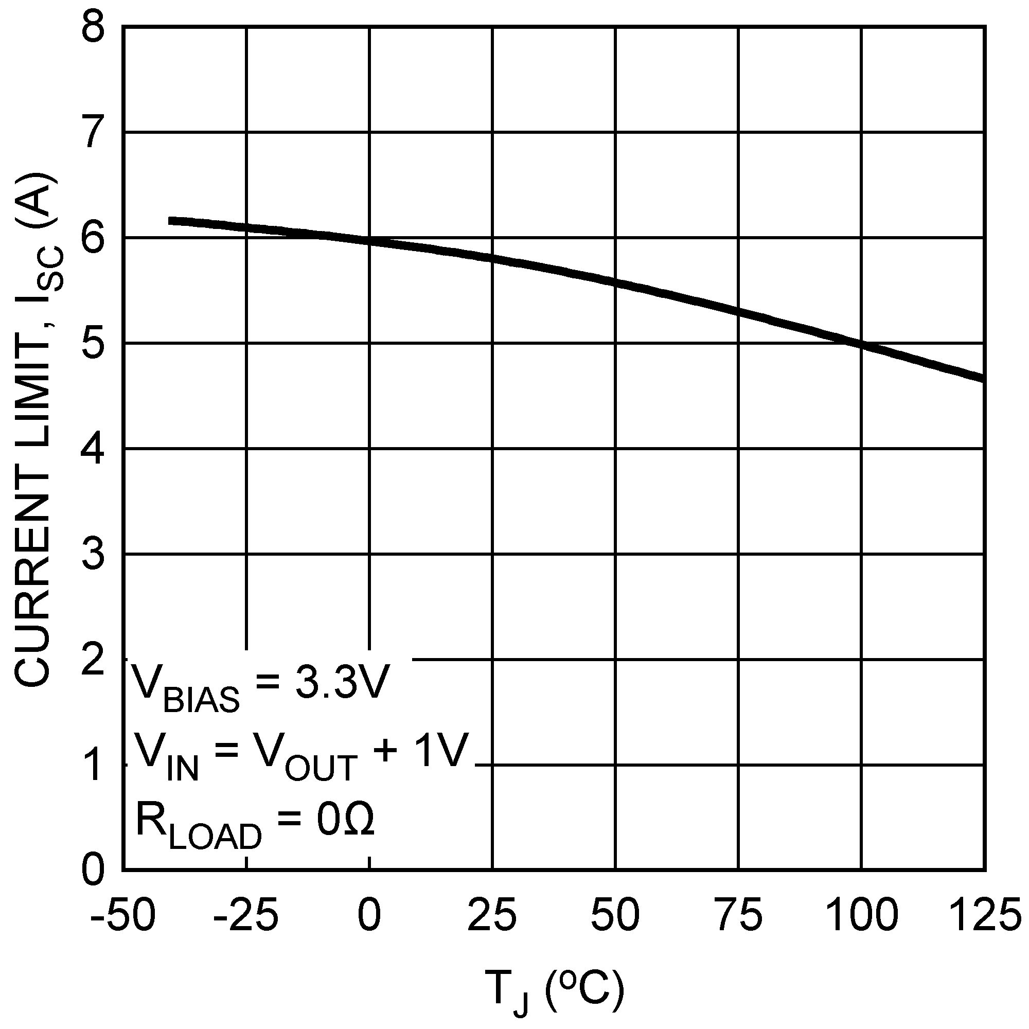 Figure 6. Output Current Limit (ISC) vs Temperature
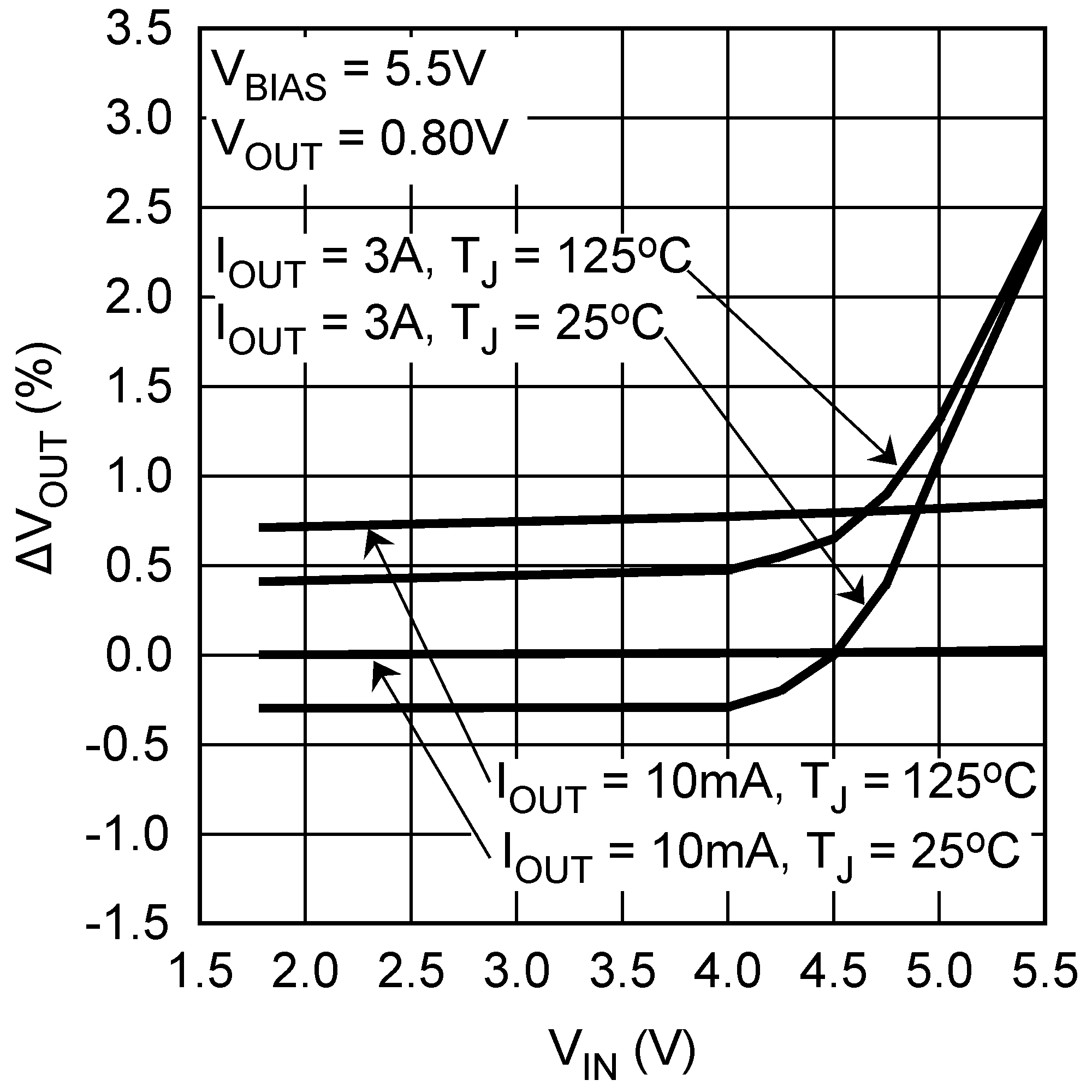 Figure 8. VOUT vs VIN
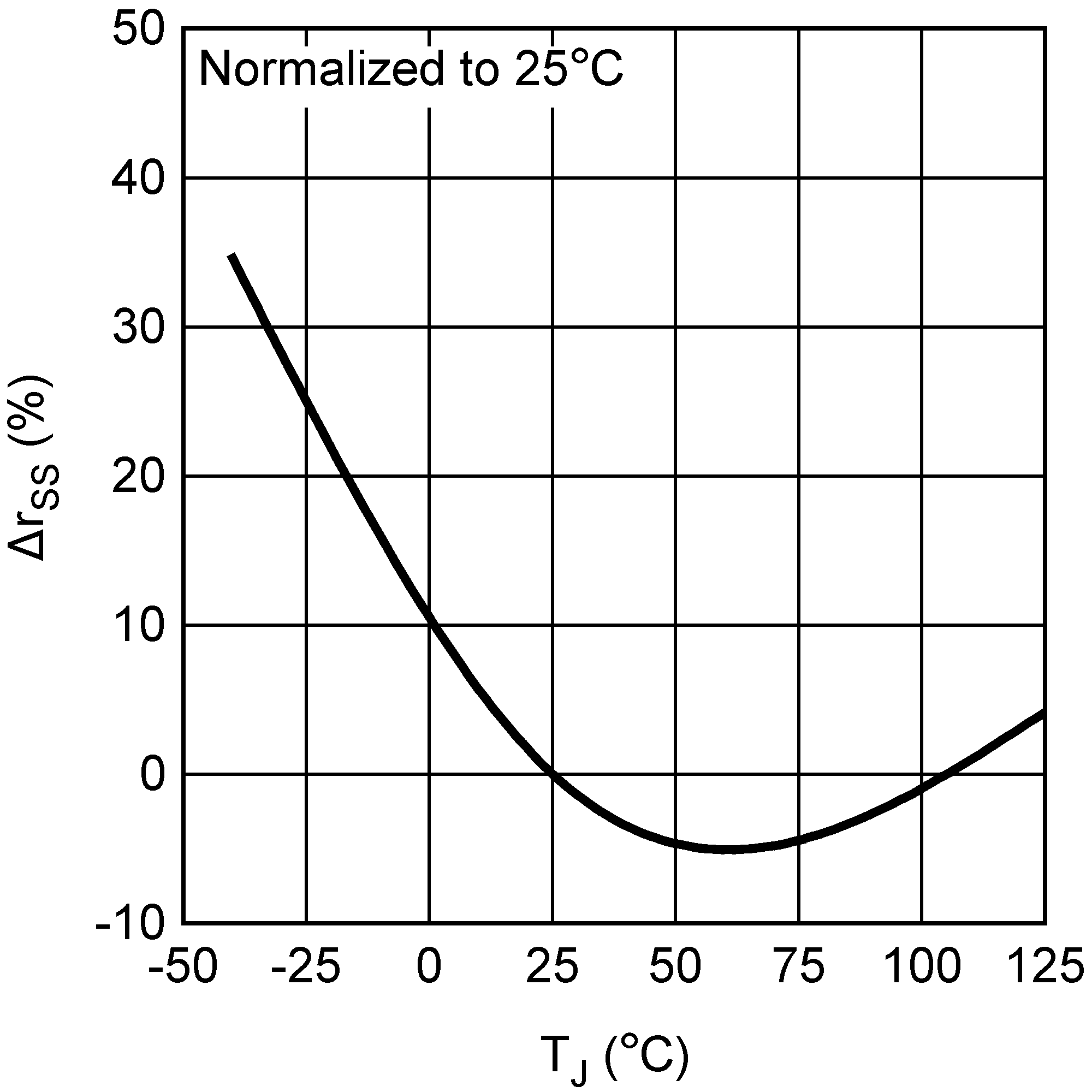 Figure 10. Soft-Start RSS Variation vs Temperature
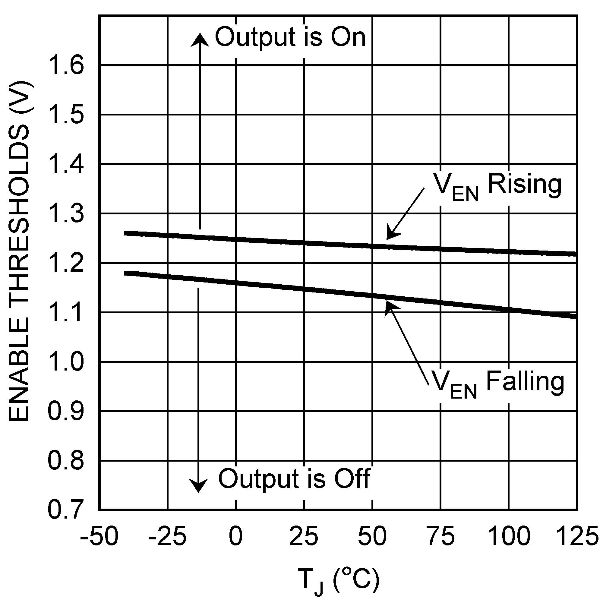
Figure 12. Enable Thresholds (VEN) vs Temperature
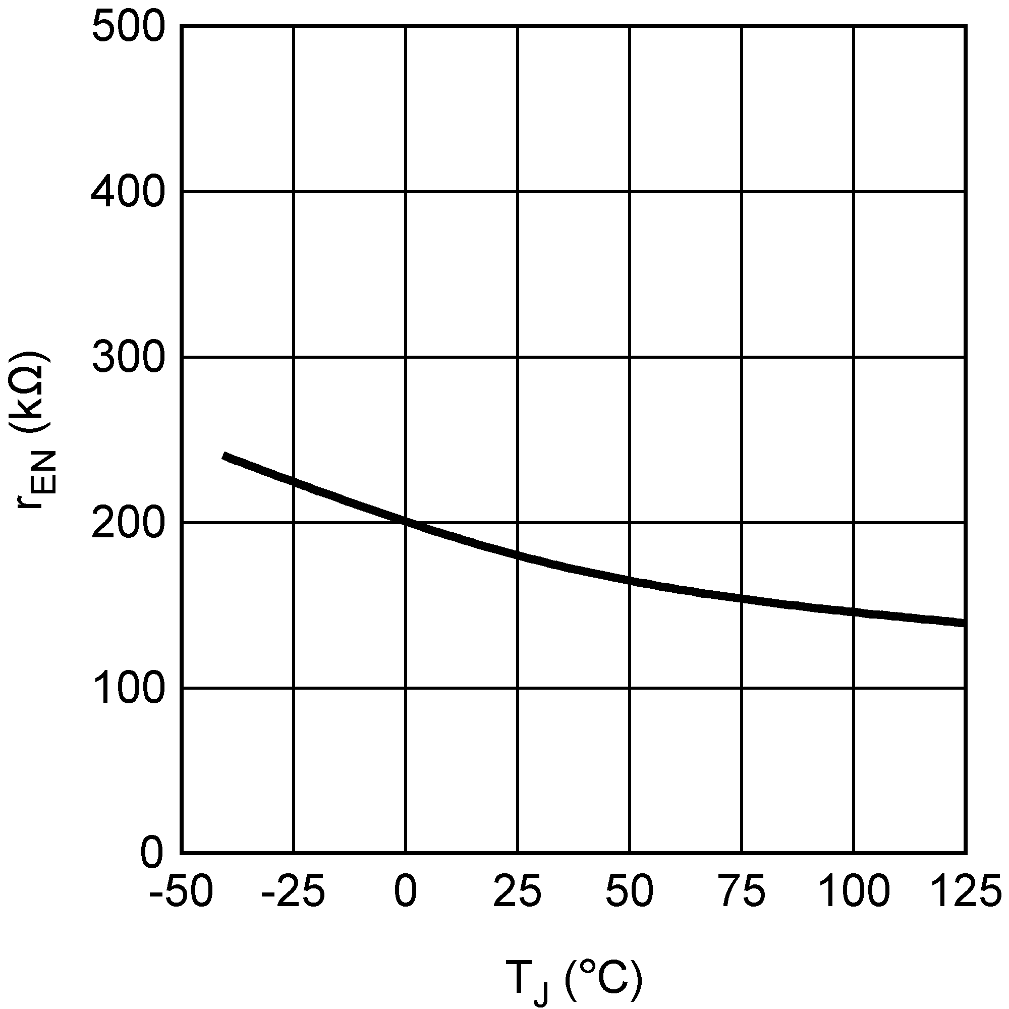
Figure 14. Enable Pullup Resistor (REN) vs Temperature
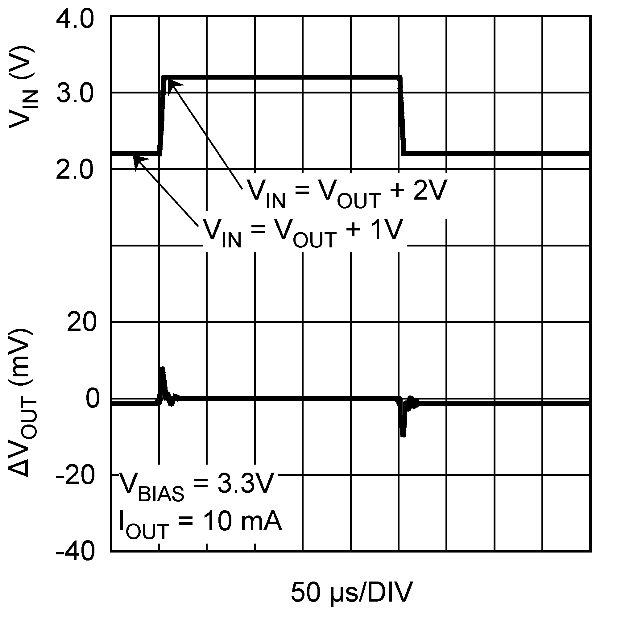
Figure 16. VIN Line Transient Response
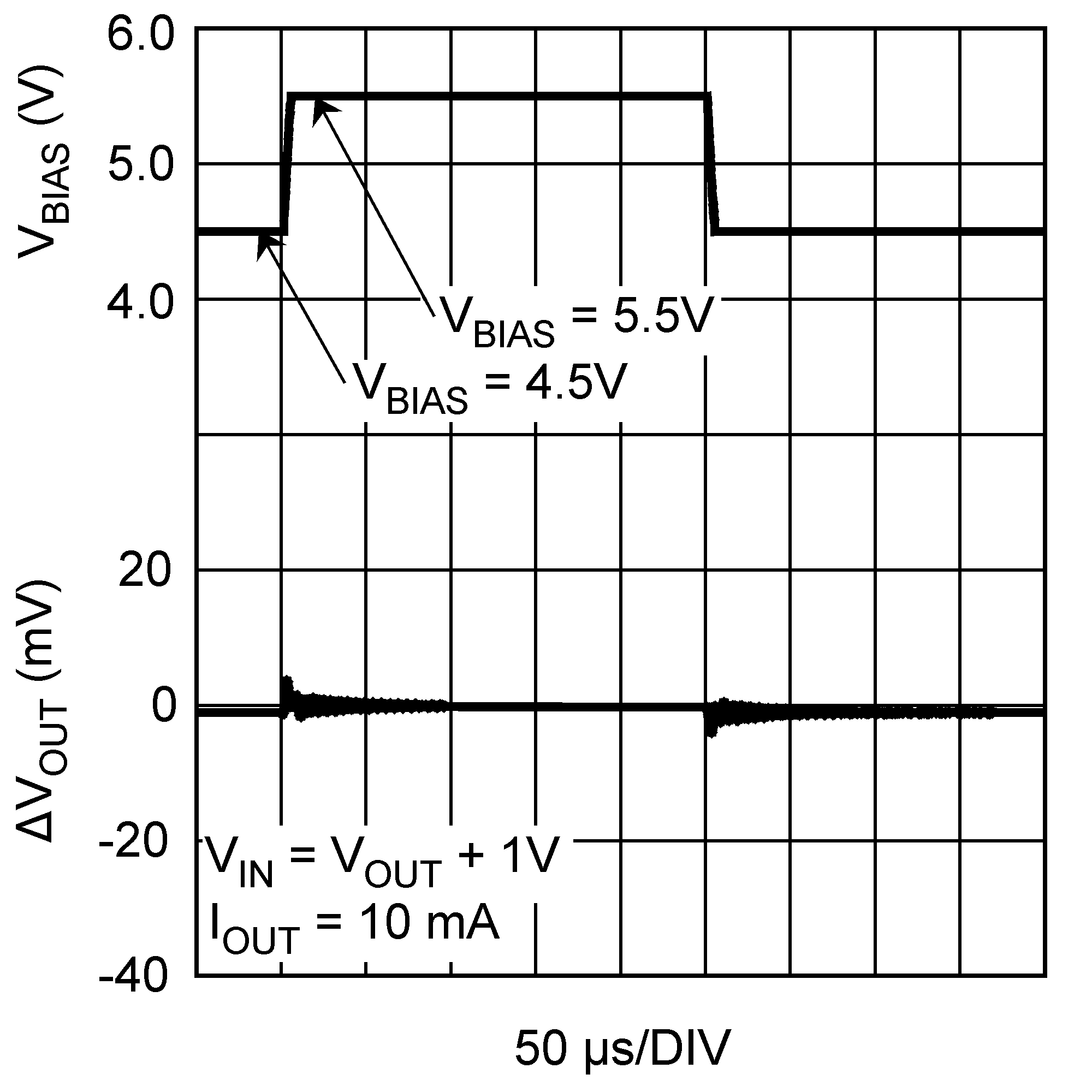
Figure 18. VBIAS Line Transient Response
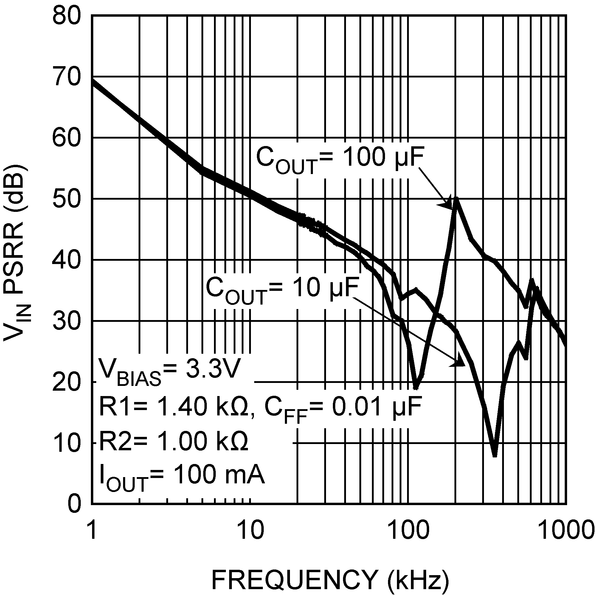
Figure 20. VIN PSRR