SLTS278J November 2010 – March 2020 PTH08T250W
PRODUCTION DATA.
- 1 Features
- 2 Applications
- 3 Description
- 4 Revision History
- 5 Description (continued)
- 6 Pin Configuration and Functions
- 7 Specifications
- 8 Detailed Description
-
9 Application and Implementation
- 9.1
Typical Application
- 9.1.1
Detailed Design Procedure
- 9.1.1.1 Adjusting the Output Voltage
- 9.1.1.2
Capacitor Recommendations for the PTH08T250W Power Module
- 9.1.1.2.1 Capacitor Technologies
- 9.1.1.2.2 Input Capacitor (Required)
- 9.1.1.2.3 Input Capacitor Information
- 9.1.1.2.4 Output Capacitor (Required)
- 9.1.1.2.5 Output Capacitor Information
- 9.1.1.2.6 TurboTrans Output Capacitance
- 9.1.1.2.7 Non-TurboTrans Output Capacitance
- 9.1.1.2.8 Designing for Fast Load Transients
- 9.1.1.2.9 Capacitor Table
- 9.1.1.3 TurboTrans™ Technology
- 9.1.1.4 TurboTrans™ Selection
- 9.1.1.5 Undervoltage Lockout (UVLO)
- 9.1.1.6 On/Off Inhibit
- 9.1.1.7 Current Sharing
- 9.1.1.8 Prebias Startup Capability
- 9.1.1.9 SmartSync Technology
- 9.1.1.10 Auto-Track™ Function
- 9.1.1
Detailed Design Procedure
- 9.1
Typical Application
- 10Device and Documentation Support
- 11Mechanical, Packaging, and Orderable Information
デバイスごとのパッケージ図は、PDF版データシートをご参照ください。
メカニカル・データ(パッケージ|ピン)
- BCU|22
- ECT|22
- ECU|22
サーマルパッド・メカニカル・データ
5 Description (continued)
The device includes TurboTrans and the new patent-pending SmartSync technologies. The TurboTrans feature optimizes the transient response of the regulator while simultaneously reducing the quantity of external output capacitors required to meet a target voltage deviation specification. Additionally, for a target output capacitor bank, TurboTrans technology can be used to significantly improve the regulators transient response by reducing the peak voltage deviation. SmartSync technology allows for switching frequency synchronization of multiple modules, thus simplifying EMI noise suppression tasks and reducing input capacitor RMS current requirements.
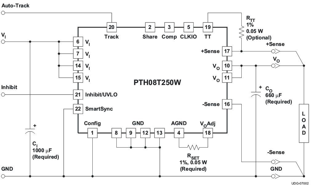
RSET is required to set the output voltage higher than 0.7 V. See the Electrical Characteristics table for more information.
Double-sided surface mount construction provides a low profile and compact footprint. Package options include both through-hole and surface mount configurations that are lead (Pb)-free and RoHS compatible.
