SLTS278J November 2010 – March 2020 PTH08T250W
PRODUCTION DATA.
- 1 Features
- 2 Applications
- 3 Description
- 4 Revision History
- 5 Description (continued)
- 6 Pin Configuration and Functions
- 7 Specifications
- 8 Detailed Description
-
9 Application and Implementation
- 9.1
Typical Application
- 9.1.1
Detailed Design Procedure
- 9.1.1.1 Adjusting the Output Voltage
- 9.1.1.2
Capacitor Recommendations for the PTH08T250W Power Module
- 9.1.1.2.1 Capacitor Technologies
- 9.1.1.2.2 Input Capacitor (Required)
- 9.1.1.2.3 Input Capacitor Information
- 9.1.1.2.4 Output Capacitor (Required)
- 9.1.1.2.5 Output Capacitor Information
- 9.1.1.2.6 TurboTrans Output Capacitance
- 9.1.1.2.7 Non-TurboTrans Output Capacitance
- 9.1.1.2.8 Designing for Fast Load Transients
- 9.1.1.2.9 Capacitor Table
- 9.1.1.3 TurboTrans™ Technology
- 9.1.1.4 TurboTrans™ Selection
- 9.1.1.5 Undervoltage Lockout (UVLO)
- 9.1.1.6 On/Off Inhibit
- 9.1.1.7 Current Sharing
- 9.1.1.8 Prebias Startup Capability
- 9.1.1.9 SmartSync Technology
- 9.1.1.10 Auto-Track™ Function
- 9.1.1
Detailed Design Procedure
- 9.1
Typical Application
- 10Device and Documentation Support
- 11Mechanical, Packaging, and Orderable Information
デバイスごとのパッケージ図は、PDF版データシートをご参照ください。
メカニカル・データ(パッケージ|ピン)
- BCU|22
- ECT|22
- ECU|22
サーマルパッド・メカニカル・データ
8.2.1 Soft-Start Power-Up
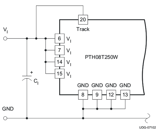
The Auto-Track feature allows the power-up of multiple PTH/PTV modules to be directly controlled from the Track pin. However in a stand-alone configuration, or when the Auto-Track feature is not being used, the Track pin should be directly connected to the input voltage, VI (see Figure 11).
 Figure 11. Defeating the Auto-Track Function
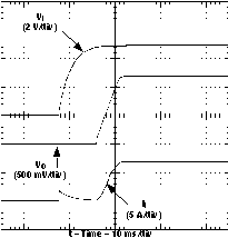
  Figure 12. Power-Up Waveform
 When the Track pin is connected to the input voltage the Auto-Track function is permanently disengaged. This allows the module to power up entirely under the control of its internal soft-start circuitry. When power up is under soft-start control, the output voltage rises to the set-point at a quicker and more linear rate.
From the moment a valid input voltage is applied, the soft-start control introduces a short time delay (a period typically between 10 ms and 15 ms) before allowing the output voltage to rise.
The output then progressively rises to the setpoint voltage of the module. Figure 12 shows the soft-start power-up characteristic of the PTH08T250W operating from a 5-V input bus and configured for a 1.2-V output. The waveforms were measured with a 25-A constant current load and the Auto-Track feature disabled. The initial rise in input current when the input voltage first starts to rise is the charge current drawn by the input capacitors. Power-up is complete within 30 ms.