JAJSFI3A May 2018 – November 2018 TAS3251
PRODUCTION DATA.
- 1 特長
- 2 アプリケーション
- 3 概要
- 4 改訂履歴
- 5 Device Comparison Table
- 6 Pin Configuration and Functions
-
7 Specifications
- 7.1 Absolute Maximum Ratings
- 7.2 ESD Ratings
- 7.3 Recommended Operating Conditions
- 7.4 Thermal Information
- 7.5 Amplifier Electrical Characteristics
- 7.6 DAC Electrical Characteristics
- 7.7 Audio Characteristics (BTL)
- 7.8 Audio Characteristics (PBTL)
- 7.9 MCLK Timing
- 7.10 Serial Audio Port Timing – Slave Mode
- 7.11 Serial Audio Port Timing – Master Mode
- 7.12 I2C Bus Timing –Standard
- 7.13 I2C Bus Timing –Fast
- 7.14 Timing Diagrams
- 7.15 Typical Characteristics
-
8 Detailed Description
- 8.1 Overview
- 8.2 Functional Block Diagram
- 8.3
Feature Description
- 8.3.1 Power-on-Reset (POR) Function
- 8.3.2 Enable Device
- 8.3.3 DAC and DSP Clocking
- 8.3.4
Serial Audio Port
- 8.3.4.1 Clock Master Mode from Audio Rate Master Clock
- 8.3.4.2 Clock Slave Mode with 4-Wire Operation (SCLK, MCLK, LRCK/FS, SDIN)
- 8.3.4.3 Clock Slave Mode with SCLK PLL to Generate Internal Clocks (3-Wire PCM)
- 8.3.4.4 Serial Audio Port – Data Formats and Bit Depths
- 8.3.4.5 Input Signal Sensing (Power-Save Mode)
- 8.3.5 Volume Control
- 8.3.6 SDOUT Port and Hardware Control Pin
- 8.3.7 I2C Communication Port
- 8.3.8 Pop and Click Free Startup and Shutdown
- 8.3.9 Integrated Oscillator for Output Power Stage
- 8.3.10
Device Output Stage Protection System
- 8.3.10.1 Error Reporting
- 8.3.10.2 Overload and Short Circuit Current Protection
- 8.3.10.3 Signal Clipping and Pulse Injector
- 8.3.10.4 DC Speaker Protection
- 8.3.10.5 Pin-to-Pin Short Circuit Protection (PPSC)
- 8.3.10.6 Overtemperature Protection OTW and OTE
- 8.3.10.7 Undervoltage Protection (UVP) and Power-on Reset (POR)
- 8.3.10.8 Fault Handling
- 8.3.10.9 Output Power Stage Reset
- 8.3.11
Initialization, Startup and Shutdown
- 8.3.11.1 Power Up and Startup Sequence
- 8.3.11.2 Power Down and Shutdown Sequence
- 8.3.11.3 Device Mute
- 8.3.11.4 Device Unmute
- 8.3.11.5 Device Reset
- 8.3.11.6 Mute with DAC_MUTE or Clock Error
- 8.3.11.7 Mute using Serial Audio Port Clock
- 8.3.11.8 Muting before an Unplanned Shutdown with DAC_MUTE
- 8.3.11.9 Output Power Stage Startup Timing
- 8.4 Device Functional Modes
- 8.5
Programming
- 8.5.1 Audio Processing Features
- 8.5.2 Processing Block Description
- 8.5.3 Other Processing Block Features
- 8.5.4 Checksum
- 8.6
Register Maps
- 8.6.1
Registers - Page 0
- 8.6.1.1 Register 1 (0x01)
- 8.6.1.2 Register 2 (0x02)
- 8.6.1.3 Register 3 (0x03)
- 8.6.1.4 Register 4 (0x04)
- 8.6.1.5 Register 6 (0x06)
- 8.6.1.6 Register 7 (0x07)
- 8.6.1.7 Register 8 (0x08)
- 8.6.1.8 Register 9 (0x09)
- 8.6.1.9 Register 12 (0x0C)
- 8.6.1.10 Register 13 (0x0D)
- 8.6.1.11 Register 14 (0x0E)
- 8.6.1.12 Register 15 (0x0F)
- 8.6.1.13 Register 16 (0x10)
- 8.6.1.14 Register 17 (0x11)
- 8.6.1.15 Register 18 (0x12)
- 8.6.1.16 Register 20 (0x14)
- 8.6.1.17 Register 21 (0x15)
- 8.6.1.18 Register 22 (0x16)
- 8.6.1.19 Register 23 (0x17)
- 8.6.1.20 Register 24 (0x18)
- 8.6.1.21 Register 27 (0x1B)
- 8.6.1.22 Register 28 (0x1C)
- 8.6.1.23 Register 29 (0x1D)
- 8.6.1.24 Register 30 (0x1E)
- 8.6.1.25 Register 32 (0x20)
- 8.6.1.26 Register 33 (0x21)
- 8.6.1.27 Register 34 (0x22)
- 8.6.1.28 Register 37 (0x25)
- 8.6.1.29 Register 40 (0x28)
- 8.6.1.30 Register 41 (0x29)
- 8.6.1.31 Register 42 (0x2A)
- 8.6.1.32 Register 43 (0x2B)
- 8.6.1.33 Register 44 (0x2C)
- 8.6.1.34 Register 59 (0x3B)
- 8.6.1.35 Register 60 (0x3C)
- 8.6.1.36 Register 61 (0x3D)
- 8.6.1.37 Register 62 (0x3E)
- 8.6.1.38 Register 63 (0x3F)
- 8.6.1.39 Register 64 (0x40)
- 8.6.1.40 Register 65 (0x41)
- 8.6.1.41 Register 67 (0x43)
- 8.6.1.42 Register 68 (0x44)
- 8.6.1.43 Register 69 (0x45)
- 8.6.1.44 Register 70 (0x46)
- 8.6.1.45 Register 71 (0x47)
- 8.6.1.46 Register 72 (0x48)
- 8.6.1.47 Register 73 (0x49)
- 8.6.1.48 Register 74 (0x4A)
- 8.6.1.49 Register 75 (0x4B)
- 8.6.1.50 Register 76 (0x4C)
- 8.6.1.51 Register 78 (0x4E)
- 8.6.1.52 Register 79 (0x4F)
- 8.6.1.53 Register 85 (0x55)
- 8.6.1.54 Register 86 (0x56)
- 8.6.1.55 Register 87 (0x57)
- 8.6.1.56 Register 88 (0x58)
- 8.6.1.57 Register 91 (0x5B)
- 8.6.1.58 Register 92 (0x5C)
- 8.6.1.59 Register 93 (0x5D)
- 8.6.1.60 Register 94 (0x5E)
- 8.6.1.61 Register 95 (0x5F)
- 8.6.1.62 Register 108 (0x6C)
- 8.6.1.63 Register 119 (0x77)
- 8.6.1.64 Register 120 (0x78)
- 8.6.2 Registers - Page 1
- 8.6.1
Registers - Page 0
-
9 Application and Implementation
- 9.1
Typical Applications
- 9.1.1 Stereo, Bridge Tied Load (BTL) Application
- 9.1.2 Mono, Parallel Bridge-Tied Load (PBTL) Application
- 9.1.3 Design Requirements
- 9.1.4 Detailed Design Procedure
- 9.1.5 Two TAS3251 Device Configurations
- 9.1.6 Three or More TAS3251 Device Configurations
- 9.1.7 Application Curves
- 9.1
Typical Applications
- 10Power Supply Recommendations
- 11Layout
- 12デバイスおよびドキュメントのサポート
- 13メカニカル、パッケージ、および注文情報
8.5.2.6 Two-Band Dynamic Range Control
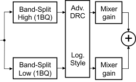
The Dynamic Range Control (DRC) is a feed-forward mechanism that can be used to automatically control the audio signal amplitude or the dynamic range within specified limits. The dynamic range control is done by sensing the audio signal level using an estimate of the alpha filter energy then adjusting the gain based on the region and slope parameters that are defined. The Dynamic Range Control is shown in Figure 47.
 Figure 47. Dynamic Range Control
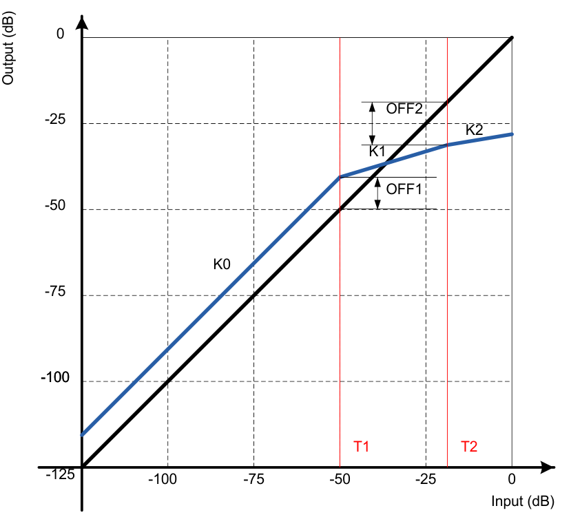
 The DRCs have seven programmable transfer function parameters each: k0, k1, k2, T1, T2, OFF1, and OFF2. The T1 and T2 parameters specify thresholds or boundaries of the three compression or expansion regions in terms of input level. The Parameters k0, k1, and k2 define the gains or slopes of curves for each of the three regions. The parameters OFF1 and OFF2 specify the offset shift relative 1:1 transfer function curve at the thresholds T1 and T2 respectively shown in Figure 48.
 Figure 48. DRC Transfer Function Example Plot
 The two-band dynamic range control is comprised of two DRCs that can be spilt into two bands using the BQ at the input of each band. The frequency where the two bands are spilt is referred to as the crossover frequency. The crossover frequency is the cut off frequency for the low pass filter used to create the low band and the cut off frequency for the high pass filter used to create the high band. It is inherent of parallel two-band DRC to have a hump at the crossover region due to the overlap of energy going through both bands of the DRC being summed in the two-band DRC output mixer.
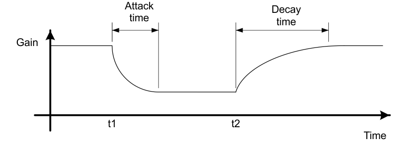
 Figure 49. DRC Attack and Decay
 The DRC in each band is equipped with individual energy, attack, and decay time constants. The DRC time constants control the transition time of changes and decisions in the DRC gain during compression or expansion. The energy, attack, and decay time constants affect the sensitivity level of the DRC. The shorter the time constant, the more aggressive the DRC response and vice versa.