JAJSVM2 November   2024 TDP142-Q1

ADVANCE INFORMATION  

  1.   1
  2. 特長
  3. アプリケーション
  4. 概要
  5. Pin Configuration and Functions
  6. Specifications
    1. 5.1 Absolute Maximum Ratings
    2. 5.2 ESD Ratings
    3. 5.3 Recommended Operating Conditions
    4. 5.4 Thermal Information
    5. 5.5 Power Supply Characteristics
    6. 5.6 Control I/O DC Electrical Characteristics
    7. 5.7 DP Electrical Characteristics
    8. 5.8 Switching Characteristics
    9. 5.9 Typical Characteristics
  7.   Parameter Measurement Information
  8. Detailed Description
    1. 6.1 Overview
    2. 6.2 Functional Block Diagram
    3. 6.3 Feature Description
      1. 6.3.1 DisplayPort
      2. 6.3.2 Configuration Jumper Levels
      3. 6.3.3 Receiver Linear Equalization
    4. 6.4 Device Functional Modes
      1. 6.4.1 Device Configuration in GPIO Mode
      2. 6.4.2 Device Configuration in I2C Mode
      3. 6.4.3 Linear EQ Configuration
      4. 6.4.4 Operation Timing – Power Up
    5. 6.5 Programming
  9. Register Maps
    1. 7.1 TDP142-Q1 Registers
  10. Application and Implementation
    1. 8.1 Application Information
      1. 8.1.1 ESD Protection
    2. 8.2 Typical Application
      1. 8.2.1 Source Application Implementation
        1. 8.2.1.1 Design Requirement
        2. 8.2.1.2 Detail Design Procedure
      2. 8.2.2 Sink Application Implementation
        1. 8.2.2.1 Design Requirements
        2. 8.2.2.2 Detailed Design Procedure
      3. 8.2.3 Application Curve
    3. 8.3 Power Supply Recommendations
    4. 8.4 Layout
      1. 8.4.1 Layout Guidelines
      2. 8.4.2 Layout Example
  11. Device and Documentation Support
    1. 9.1 ドキュメントの更新通知を受け取る方法
    2. 9.2 サポート・リソース
    3. 9.3 Trademarks
    4. 9.4 静電気放電に関する注意事項
    5. 9.5 用語集
  12. 10Revision History
  13. 11Mechanical, Packaging, and Orderable Information
    1. 11.1 Tape and Reel Information
    2. 11.2 Mechanical Data

パッケージ・オプション

メカニカル・データ(パッケージ|ピン)
サーマルパッド・メカニカル・データ
発注情報

Layout Example

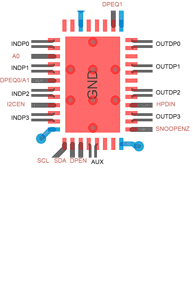
TDP142-Q1 Layout ExampleFigure 8-6 Layout Example

The following figures demonstrate the solution of mismatched order between the output of the device and the DisplayPort connector for the source using BGA package. Figure 8-7 shows the crossing section between TDP142-Q1 and connector. Usually, vias are applied to avoid the cross, but using a via can attenuate the signal integrity. Therefore, the polarity swap can be implemented at the input of TDP142-Q1. Figure 8-8 shows there is no more crossing section between the TDP142-Q1 and connector, which can minimize the number of vias being used. Note that the solution is only useful for the source using BGA package.


TDP142-Q1 Layout Example: Signal Crossing on the
          Output
Figure 8-7 Layout Example: Signal Crossing on the Output

TDP142-Q1 Layout Example: INDP2 and INDP3
          Polarity Swap
Figure 8-8 Layout Example: INDP2 and INDP3 Polarity Swap